Measuring and Test Circuit
IR_DETECTOR_CIRCUIT
Published:2009/6/19 4:13:00 Author:May | From:SeekIC

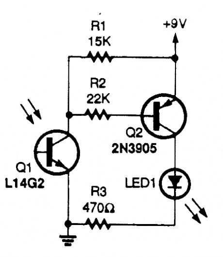
The circuit uses an IR phototransistor, Q1, to detect a remote control's IR output signal. A PNP transistor, Q2, then amplifies Q1's output and lights LED1. That indicates that an infrared signal has been detected by the phototransistor, or in other words, that your remote control works.
Reprinted Url Of This Article:
http://www.seekic.com/circuit_diagram/Measuring_and_Test_Circuit/IR_DETECTOR_CIRCUIT.html
Print this Page | Comments | Reading(3)

Article Categories
power supply circuit
Amplifier Circuit
Basic Circuit
LED and Light Circuit
Sensor Circuit
Signal Processing
Electrical Equipment Circuit
Control Circuit
Remote Control Circuit
A/D-D/A Converter Circuit
Audio Circuit
Measuring and Test Circuit
Communication Circuit
Computer-Related Circuit
555 Circuit
Automotive Circuit
Repairing Circuit
Code: