Measuring and Test Circuit
AUDIBLE_IR_DETECTOR
Published:2009/6/19 4:03:00 Author:May | From:SeekIC

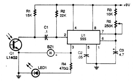
An IR-detector circuit offers an audible (as well as a visual) output, and also stretches the on time of the detected pulse to make the output easier to see, as shown.Photoresistor Q1 detects a remote's IR output pulse and sends a negative-going pulse to the trig-ger input (pin) of the 555IC, U1. The 555 is connected in a one-shot timer circuit; the output (pin 3) on time is set by the values of C3, R3, and R5 When an input pulse is detected, pin 3 goes high, lighting LED1 and activating the piezo buzzer, BZ1.For longer output pulses, set R5 to its maximum resistance value. To lengthen the circuit's on-time range, increase the value of C3, and to shorten the on-time range lower the value of C3.
Reprinted Url Of This Article:
http://www.seekic.com/circuit_diagram/Measuring_and_Test_Circuit/AUDIBLE_IR_DETECTOR.html
Print this Page | Comments | Reading(3)

Article Categories
power supply circuit
Amplifier Circuit
Basic Circuit
LED and Light Circuit
Sensor Circuit
Signal Processing
Electrical Equipment Circuit
Control Circuit
Remote Control Circuit
A/D-D/A Converter Circuit
Audio Circuit
Measuring and Test Circuit
Communication Circuit
Computer-Related Circuit
555 Circuit
Automotive Circuit
Repairing Circuit
Code: