
Circuit Diagram
Index 1753
Light load Energy Saver of Motor(the 1st)
Published:2011/5/19 8:04:00 Author:Felicity | Keyword: Light load Energy Saver of Motor,

Work of the circuit
Once it is powered, 380V AV voltage will be supplied to motor M through reator LTl-LT3. In the same time current transformer TA will produce sensor signal voltage which will make V1 and V2 saturated conducted. Then the motor will work with full voltage. When the motor is work it maybe has light load or even no load. So the sensor signal voltage on current transformer TA will reduce and this leads to the motor's decompressed operation. When the motor's load is becoming heavier, and the sensor signal voltage on current transformer TA reaches a vertain figure, the motor will work with full voltage. (View)
View full Circuit Diagram | Comments | Reading(593)
Ozone Sterilizer(the 6th)
Published:2011/5/19 8:07:00 Author:Felicity | Keyword: Ozone sterilizer,
Work of the Ozone Sterilizer Circuit
The ozone sterilizer circuit consists of Power circuit, oscillator circuit and ozone generator circuit (showed in picture 9-103).
Turn on the Timer Q and the +6V voltage will be produced after the 220V AC voltage is bucked, rectified, rectified and filtered by C1,VS,VD and C2. This voltage will supply IC and ozone generator circuit. When the low-frequency oscillator works the high-frequency oscillator is pulse modulated. Modulated pulse signal goes through R7 to the base added to V and makes V intermittently conducted. In the secondary winding to T generates pulsed high voltage and VG produces ozone in the role of high-frequency high-voltage. (View)
View full Circuit Diagram | Comments | Reading(639)
Ozone sterilizer (the 8th)
Published:2011/5/19 8:01:00 Author:Felicity | Keyword: Ozone sterilizer,
Work of the circuit
The ozone sterilizer circuit consists of power circuit, timing control circuit, and the ozone generator circuit (showed in picture 9-105).
When we Turn the power switch S the 220V cross voltage is bucked, regulated, rectified and filtered by C8,VS,VDl and CI. And then it produces +l2V voltage. It turns into two parts. One supplies the timing control circuit while the other one lightens VL after being bucked and limited by R7.
The Oscillation signal generated by ICL Internal Oscillator (which consisters of ICL,RL,RPL and C3) is outputed prom pin 2 through internal divider. Then make it Intermittently conducted between V1 and V2. In that way the ozone generator circuit intermittently gets power and works. (View)
View full Circuit Diagram | Comments | Reading(656)
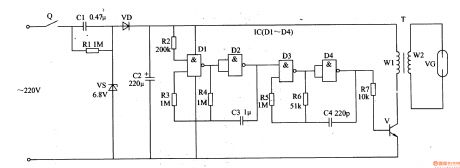
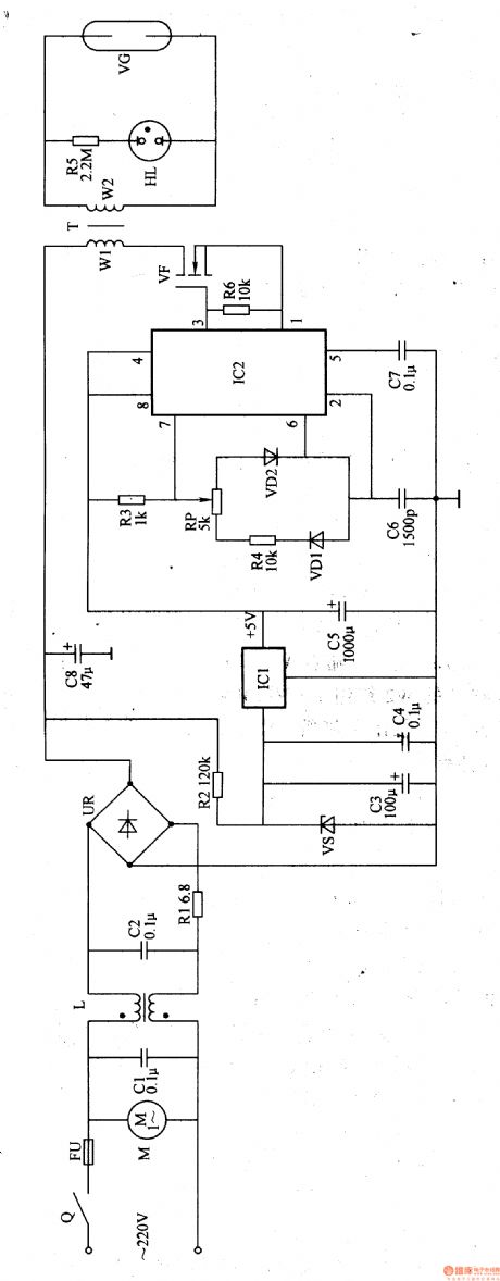
Ozone Sterilizer (the 4th)
Published:2011/5/19 8:10:00 Author:Felicity | Keyword: Ozone Sterilizer (the 4th)
Work of the Ozone Sterilizer Circuit
The ozone sterilizer circuit consists of Power circuit, timing control circuit and ozone generator circuit (showed in picture 9-101).
Turn on the Timer Q and the +12V voltage will be produced after the 220V AC voltage is bucked, rectified, rectified and filtered by C1,C2,VDl-VD4 and VS. The voltage then separates into two parts. One provides power to the timing control circuit while the other one lightens VL1 after being bucked and limited by R2. When you sterilize you should press button S2 and make the ozone generator circuit work. VT intermittently conducts and makes The LC series resonant circuit operates. Then it will generate pulsed high voltage in winding W2 and VG tube produces ozone through discharging. (View)
View full Circuit Diagram | Comments | Reading(1896)
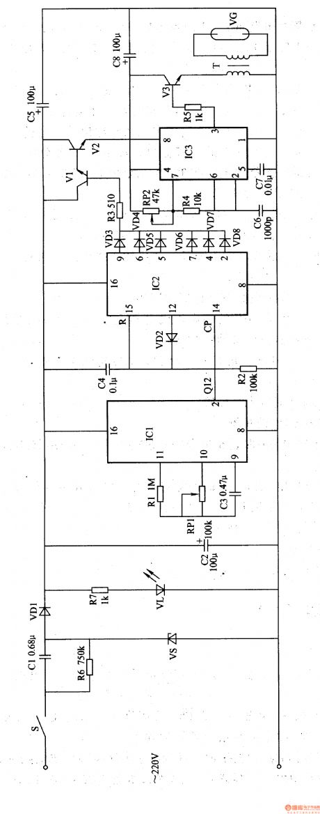
Ozone Sterilizer (the 3th)
Published:2011/5/19 8:12:00 Author:Felicity | Keyword: Ozone Sterilizer (the 3th),
Work of the Ozone Sterilizer Circuit
The ozone sterilizer circuit consists of Power circuit, timing control circuit and high-voltage circuit (showed in picture 9-100).
The 220V AC voltage will produce 12V DC voltage after bunched by T and rectified by VD1 and VD2. When it is not the right time VD4 and VD5 is off due to the low positive terminal. Oscillator which consists of IC2, RP1 and C3 works and generates l5kHz oscillation signal. It produces pulsed high voltage by boost module IC3 and the ozone is produced by ozone tube. When the regular time ends the high voltage on VG disappears. (View)
View full Circuit Diagram | Comments | Reading(1324)
Ozone Sterilizer (the 2nd)
Published:2011/5/19 8:14:00 Author:Felicity | Keyword: Ozone Sterilizer (the 2nd)
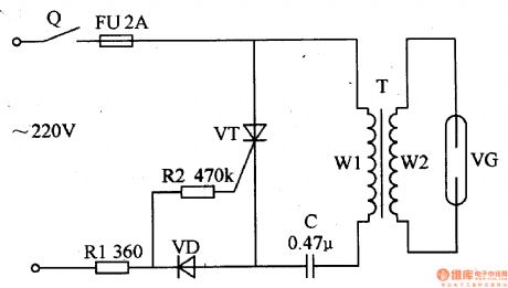
Work of the Ozone Sterilizer Circuit
When we turn on the timer Q the 220V AC voltage is limited and bucked by R1 and separate into two parts. One is supplied to VT's gate through R2 while the other one is supplied between VT's anode and cathode and makes VT conducted in AC's positive half cycle and stopped in AC's negative half cycle. With the intermittent work of VT and C step-up transformer T's winding W2 will produce pulse high voltage. Put this voltage on VG to make it produce ozone. (View)
View full Circuit Diagram | Comments | Reading(626)
Ozone Sterilizer (the 1st)
Published:2011/5/30 6:13:00 Author:Felicity | Keyword: Ozone Sterilizer (the 1st),
Work of the circuit
The ozone sterilizer circuit consists of Power circuit, oscillator circuit and ozone generator circuit (showed in picture 9-98).Turn on the timer Q and the fan motor starts to work. The 220V AC voltage transforms into 300V DC voltage. The voltage will separate into two parts. One is supplied to ozone production circuit while the other one supplies +5V working voltage to high-frequency generator being bucked, stabilized, filtered and re-stabilized by R2, VS, C3 and ICl. When the high-frequency generator works impulse high voltage is produced. The impulse high voltage is pressed on ozone tube VG. Make VC produce ozone of a certain potency which is eliminate by fan or air pump. Ifthe regular time is over timer Qwill beturned off. Then the power is cut off. (View)
View full Circuit Diagram | Comments | Reading(561)
TL082 formed Ni-Cd battery automatic charge and discharge circuit diagram
Published:2011/6/1 5:12:00 Author:Crystal Liu | Keyword: Ni-Cd battery, automatic charge and discharge

This circuit can make two cadmium nickel battery 3V or discharge in charges to 1.34V. when charge or discharge circuit automatically cut off, effectively to preventthe phenomenon of charge or discharge. (View)
View full Circuit Diagram | Comments | Reading(2000)
Disinfectant Manufacturer (the 4th)
Published:2011/5/19 21:13:00 Author:Felicity | Keyword: Disinfectant Manufacturer (the 4th),
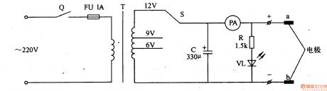
Work of the circuit
The Disinfectant Manufacturer Circuit consists of timer Q, fuse box FU, voltage transit switch S, mains transformer T, filtering fuse box C, ammeter PA, electrical resistor R, diode VL and pole a, b. (It is showed in picture 9-95)
When we use it we should put pole a, b in a container which has salt solution in it and turn on timer Q. 220V AC voltage is separated into two parts after being reduced and filtered by T and C. one is supplied to pole a, b while the other one lightens VL.
When the regular time is over Q is turned off. And it willcut off the power. Then the disinfectant is manufactured. (View)
View full Circuit Diagram | Comments | Reading(415)
LM324 formed after first discharge charge function battery charger diagram
Published:2011/6/1 5:10:00 Author:Crystal Liu | Keyword: after first discharge charge function , battery charger

This circuit in charge of cadmium nickel batteries before discharge,in order to eliminate memory effect,put the electric switch to automatically after charging status.Chargemode for width modulation constant flow,Pulse constant-current charge and pulse discharge,test battery ends voltage after filled,and a double control, parallel charge, with Counter-attack charge function.
(View)
View full Circuit Diagram | Comments | Reading(4281)
Ni-Cd battery charge circuit consist of CD4040
Published:2011/6/1 5:16:00 Author:Crystal Liu | Keyword: Ni-Cd battery charge circuit , CD4040
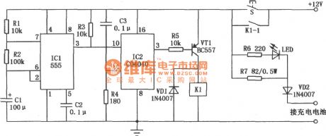
CD4040 counter chipformed the cadmium nickel battery charger as show in the picture. It can chargefor four quarter of cadmium nickel battery whoes capacity is 500mA , charge current charging time for 50mA, for l. five hours, and after finishing with charging the function of power. 555 time-based circuit constitute a clock signal generator, produce the l0Hz square wave signal, and its period for 6 seconds. When switching power supply, due to the 3 IC2 feet, so that the output low level VT1 semiconductor tube conduction, and make relay Kl suck close work, contact K1-1 closed, switch S in captive. Now charging current direction battery, and began to the battery. Status indicator LED lighted, said charging is ongoing.
CD4040 countermakes upfrequency divider and charging circuit. In the meanwhile, ICl switch on the power of the clock signal loss to produce the IC2 ⑩ feet, IC2 start counting. Because IC2 8192 was taken into the points: 1, therefore, only the frequency of an 8192 in counting pulse reach a IC2 feet by the (3) will only low level into high level, make VTl Kl stop work deadlines, and release the contacts K1-1, make it become disconnected from the state, bringing to a halt the charge. VD2 is used to prevent battery into circuit current reversed. (View)
View full Circuit Diagram | Comments | Reading(3046)
Electronic Thermostat Of The Automobile Air-conditioner
Published:2011/5/18 8:47:00 Author:Felicity | Keyword: Automobile Air-conditioner, Thermostat,
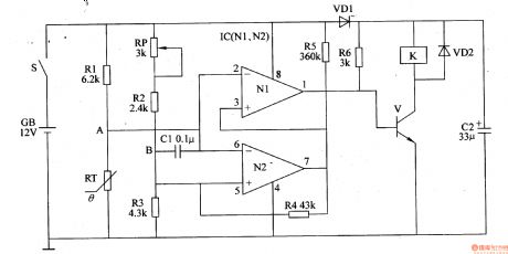
When the temperature rises in the car, the resistance of RT falls, and then the potential of A drops. When the potential of A is lower than the potential of B, the outputs of N2 and N1 are both high level, and then V is on, and the normally open contact of K is switched on. Then the clutch of air conditioner is on, then the compressor works. The air conditioning system begin to refrigerates .As the temperature falls in the car, the resistance of RT rises, and then the potential of A rises. When the potential of A is higher than the potential of B, the outputs of N2 and N1 are both low level, and V cutoff .The normally open contact of K releases, then the clutch of air conditioner is off. The refrigeration system stops work. (View)
View full Circuit Diagram | Comments | Reading(3236)
Use the timer to judgment the quality performance of photoelectric couplers
Published:2011/5/22 7:27:00 Author:Crystal Liu | Keyword: quality performance of photoelectric couplers, timer

NE555 adopted the circuit shows in figure 1 below,VD1 and VD2 role is sepatating capacitance C1 charge-discharge loop,in order to make the timer output 390v adjustable pulse waveform;C2isfilter capacitance,capacity is 0.01uF,Its role is comprised of timing devices;Resistance of R1,R2 respectively is 10kΩ and 51kΩ;The resistance of Rp is 0—10kΩ;The resistance of R3 and R4 respectively is 2kΩ and 1kΩ.Their action all is for the current limit;Vcc can use dry cell or dc voltage stabilizer.
(View)
View full Circuit Diagram | Comments | Reading(446)
Use AT89C2051 microcontroller making steamed rice ark timer switch
Published:2011/5/22 8:19:00 Author:Crystal Liu | Keyword: AT89C2051 microcontroller making steamed rice ark timer switch, AT89C2051, 7805

The circuit shows in figure 1.AT89C2051 single-chip microcomputer chip IC1 as the core of this circuit ,C3 and R10 formed simple automatic reset circuit.JT、 C1、C2 and ICl related pins formed SCM clock circuit.The display uses two share with anode type digital tube.15 I/O port of ICl all be used.Among them, the PI. 0 for seconds show lose exports,through a limited flow resistance of various digital tube connected to the decimal point electrode,during normal working,use decimal shining as seconds signal display ~P1.1-P1.7 as seven segment digital pipe section choose signal(Low-level effective) lose exports,through a limited flow resistance respectively ,connect the corresponding to the digital tube electrode.Digital pipe display dynamic scanning manner,it's dynamic bits choose signal respectively by IC P3.4 and P3.5 output ,high-level effective.
(View)
View full Circuit Diagram | Comments | Reading(5071)
M9082(TV) infrared remote control transmitting microprocessor
Published:2011/5/26 8:50:00 Author:Lena | Keyword: infrared, remote control, transmitting, microprocessor
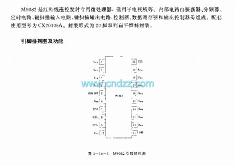
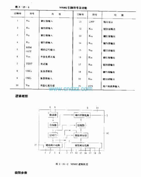

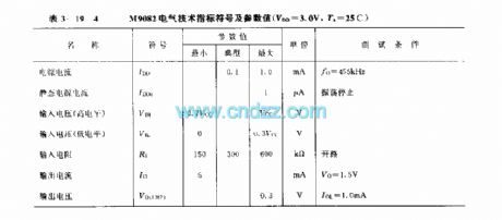
M9082 is an infrared remote control transmitting microprocessor,applied to TVs etc.Internal circuit consists of oscillator, divider, timing circuit, key scan input circuit, key scan output circuit, controller, data register and output controller. Supporting types is CX20106A.Package form is 20 pins dual flat plastic package.
(View)
View full Circuit Diagram | Comments | Reading(456)
M50163—150SP(TV) infrared remote control receiving microprocessor
Published:2011/6/1 9:36:00 Author:Lena | Keyword: infrared, remote control, receiving microprocessor
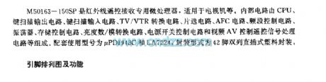
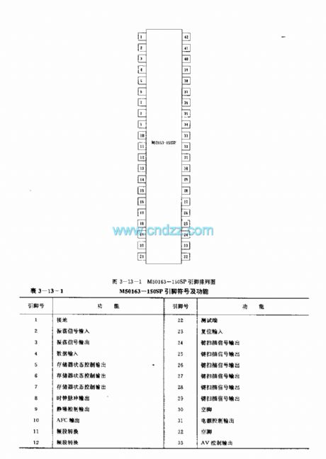
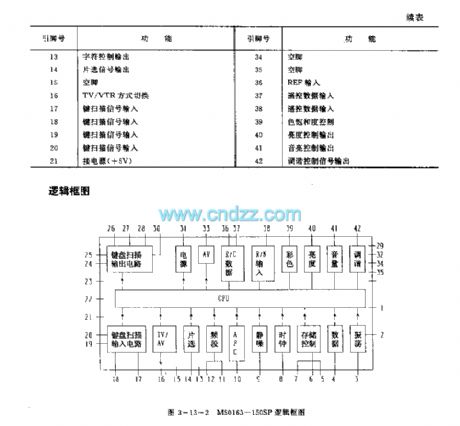
M50163-150SP is an infrared remote control receiving microprocessor which is applied to TV etc. Internal circuit consists of CPU, key scan output circuit, key scan input circuit, TV/VTR converter circuit, chip select circuit, AFC circuit, frequency band control circuit, oscillator, storage control circuit, lightness digital/mimic converter circuit, source switch control circuit and video AV control remote signal processing circuit. Related used type is CX20106A. Package model is 20-pin dual-in-line plastic package.
(View)
View full Circuit Diagram | Comments | Reading(612)
The flash circuit power supplied by the AC power grid
Published:2011/5/22 8:33:00 Author:Crystal Liu | Keyword: The flash circuit power supplied by the AC power grid, BC172B

This circuit is used for alternate hige control of 100W incandescent lamp.The Dc voltage after rectifying Ac power supply voltage add to the circuit which is series connection one-way thyristor and load La(light) .Alternate hige frequency decided much harmonic oscillator's oscillation frequency.The picture circuit parameters adjustment 2.5kΩ potentiometer can make oscillation frequency range from 0.5Hz to 1Hz,occupies emptiescompared is 0.5,light time and blackout time is the same.If change 27kΩ passive resistance(range 5~50kΩ),the occupies emptiescompared will be changed,at this time 2.5kΩ potentiometer and 2.2kΩ resistance can cancel,Passive resistance can directly meet in the power which is 12V.
(View)
View full Circuit Diagram | Comments | Reading(522)
M50462AP (TV) infrared remote control transmitting microprocessor
Published:2011/6/1 9:35:00 Author:Lena | Keyword: infrared, remote control, transmitting, microprocessor

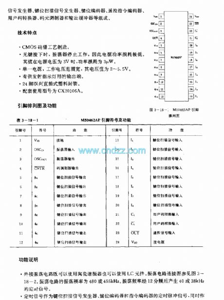
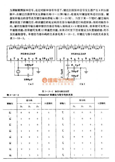
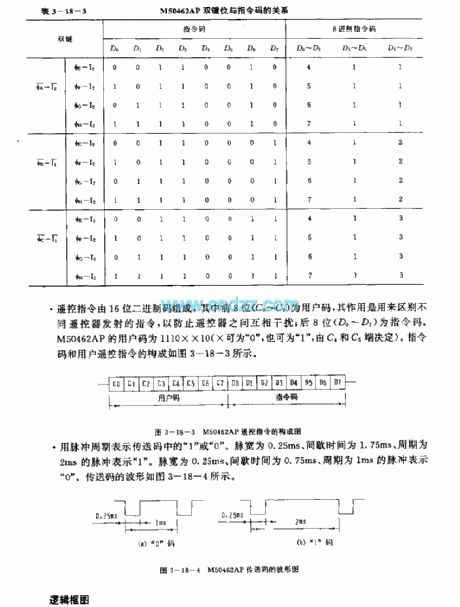
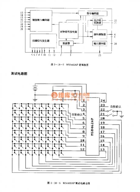
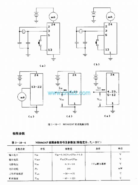
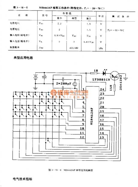
M50462AP is an infrared remote control transmitting microprocessor applied to TV etc. Internal circuit composed by oscillator, clock signal generator, key scan signal generator, key coder, remote control instruction coder, user code converter, code modulator and output buffer etc.
Technology features
Si-gate CMOS ProcessWhen no keyis pressed, the oscillator stop work, so supply power loss is very low. When power supply voltageis 3V, the loss is 3μW.Single power supply, work voltage(2-2.5V) range is wide.
(View)
View full Circuit Diagram | Comments | Reading(656)
M50460—012P(TV) infrared remote control transmitting control circuit
Published:2011/6/1 9:34:00 Author:Lena | Keyword: infrared, remote control, transmitting, control circuit


M50460-012P is an infrared remote control transmitting control integrated circuit which is applied to TV etc. Internal circuit consists of oscillator, scan signal generator, timing signal generator, instruction encoder, coding modulator, key control input coder and output buffer. Related used type is CX20106A. Package model is 20-pin dual-in-line plastic package.
Function descriptionRemote control instruction is composed by 1-bit leader code, 8-bit user code and 8-bit function code. The anterior 8-bit user code is used to identify producer and to prevent interference between remote controllers.
(View)
View full Circuit Diagram | Comments | Reading(779)
Hearing-aid (the 5th)
Published:2011/6/6 5:01:00 Author:Felicity | Keyword: Hearing-aid (the 5th)

Work of the circuit
The hearing-aid circuit consists of amplifying output circuit, volume controlling circuit and voice-frequency amplifying circuit. (It is showed in picture 9-81.).
Turn on the switch S and the machine begins to work. BM turns the sound signal it collects into electric signal. Then the electrical signal drives BE to make sound . Some of IC’s outputting signals can adjust IC’s inputting and outputting voltage after being filtered by C5, RP, VD and C3. In this way the volume can be controlled automatically.
If you change the value of RP you can change the volume. (View)
View full Circuit Diagram | Comments | Reading(4347)
| Pages:1753/2234 At 2017411742174317441745174617471748174917501751175217531754175517561757175817591760Under 20 |
Circuit Categories
power supply circuit
Amplifier Circuit
Basic Circuit
LED and Light Circuit
Sensor Circuit
Signal Processing
Electrical Equipment Circuit
Control Circuit
Remote Control Circuit
A/D-D/A Converter Circuit
Audio Circuit
Measuring and Test Circuit
Communication Circuit
Computer-Related Circuit
555 Circuit
Automotive Circuit
Repairing Circuit