
Circuit Diagram
Index 1746
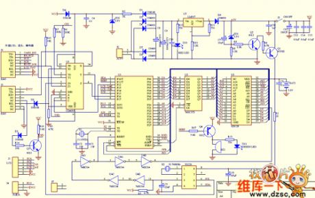
The OID time card machine circuit
Published:2011/6/19 19:58:00 Author:qqtang | Keyword: OID, time card machine
View full Circuit Diagram | Comments | Reading(715)
The switch power supply circuit
Published:2011/6/19 20:02:00 Author:qqtang | Keyword: power supply

The switch power supply circuit is shown in the figure.
(View)
View full Circuit Diagram | Comments | Reading(759)
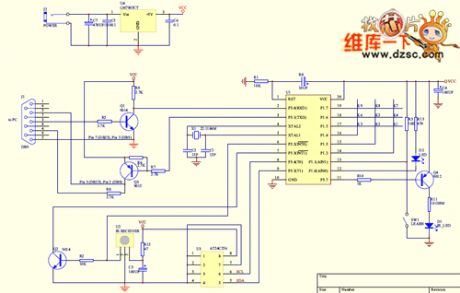
The learning infrared remote control terminal circuit
Published:2011/6/19 20:04:00 Author:qqtang | Keyword: infrared, remote control
View full Circuit Diagram | Comments | Reading(583)
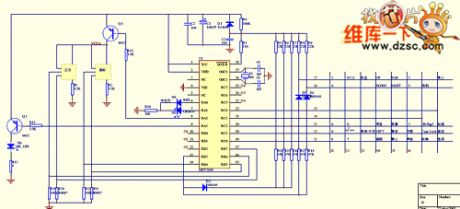
The digital answering racer design circuit
Published:2011/6/16 22:23:00 Author:qqtang | Keyword: answering racer

View full Circuit Diagram | Comments | Reading(507)
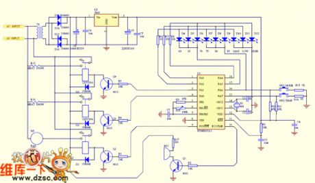
The fan heater circuit
Published:2011/6/19 19:53:00 Author:qqtang | Keyword: fan heater
View full Circuit Diagram | Comments | Reading(993)
The computer infrared remote controller circuit
Published:2011/6/19 19:55:00 Author:qqtang | Keyword: infrared, remote controller
View full Circuit Diagram | Comments | Reading(455)
The inverting switch power supply circuit
Published:2011/6/16 22:26:00 Author:qqtang | Keyword: inverting switch, power supply

The inverting switch power supply circuit is shown in the figure.
(View)
View full Circuit Diagram | Comments | Reading(569)
The electric rat exterminator circuit (2)
Published:2011/6/19 20:01:00 Author:qqtang | Keyword: rat exterminator
View full Circuit Diagram | Comments | Reading(662)
The electric rat exterminator circuit (1)
Published:2011/6/19 20:00:00 Author:qqtang | Keyword: rat exterminator
View full Circuit Diagram | Comments | Reading(721)
The switch power supply circuit consisting of the single chip switch stabilizer dn-25
Published:2011/6/16 22:31:00 Author:qqtang | Keyword: power supply, single chip, switch stabilizer

The switch power supply circuit consisting of the single chip switch stabilizer dn-25 is shown in the figure.
(View)
View full Circuit Diagram | Comments | Reading(599)
A walkie talkie circuit
Published:2011/6/16 22:28:00 Author:qqtang | Keyword: walkie talkie

View full Circuit Diagram | Comments | Reading(5068)
An air-conditioner remote control circuit
Published:2011/6/16 22:29:00 Author:qqtang | Keyword: air-conditioner, remote control

View full Circuit Diagram | Comments | Reading(621)
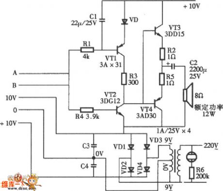
The application circuit of the stable power supply transistor switch
Published:2011/6/16 22:34:00 Author:qqtang | Keyword: application circuit, power supply

The application circuit of the stable power supply transistor switch is shown in the figure.
(View)
View full Circuit Diagram | Comments | Reading(666)
A cell phone charger circuit
Published:2011/6/16 22:36:00 Author:qqtang | Keyword: cell phone charger

View full Circuit Diagram | Comments | Reading(1128)
Inductive anti-theft alarm circuit diagram
Published:2011/6/14 5:06:00 Author:Lucas | Keyword: Inductive, anti-theft alarm

The circuit is shown as the chart. The voltage on R3 is higher to stop the multiple valve composed of V4 and V2 and conduct V2, and it cuts off the four tones analog integrated circuit, and the speaker does not sound. When someone closes to the sensor, the value of C0 increases and the high-frequency differential pressure decreases. The voltage sent to the base of V1 by C3 can not maintain the oscillation of V1 and V1 stops vibration immediately. At this point the voltage on R3 becomes smaller, and V2 stops, then V3, V4 conduct and the pin ② of IC gets power and works.Pin ③ emits siren signal which is amplified by the V5 and output from the loudspeaker, and it will emit warning sound.
(View)
View full Circuit Diagram | Comments | Reading(1087)
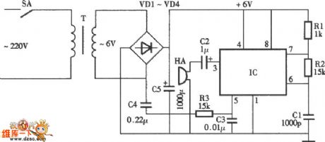
The electronic rodent repeller circuit diagram 1
Published:2011/6/14 20:30:00 Author:Lucas | Keyword: Electronic rodent repeller

The electronic rodent repeller circuit is composed of the power circuit, oscillator and piezoelectric buzzer HA, and the circuit is shown as the chart. Power circuit is composed of the power switch S, power transformer T, rectifier diodes VD1 ~ VD4 and filter capacitor C5 and so on. The oscillator is composed of time-base integrated circuit IC, resistors R1 ~ R3 and capacitors C1 ~ C3 and other components. R1 ~ R3 use 1/4W or 1/8W carbon film resistors. C1 chooses high-frequency ceramic capacitor; C2 and C5 select aluminium electrolytic capacitors with the voltage in 16V; C3 and C4 use polyester capacitors or monolithic capacitors. VD1 ~ VD4 select 1 N4007 or 1N4001 silicon rectifier diodes. IC uses NE555 time-base integrated circuit. S uses a small button self-locking switch. HA uses piezoelectric buzzer.
(View)
View full Circuit Diagram | Comments | Reading(1058)
Electronic pests killing lamp circuit diagram 8
Published:2011/6/13 5:39:00 Author:Lucas | Keyword: Electronic , pests killing lamp

The electronic pests killing lamp circuit is composed of the power supply circuit, pulse oscillator and high-voltage generator circuit, and the circuit is shown as the chart. Power supply circuit is composed of the power switch S, fuse FU, power transformer T1, rectifier diodes VD1 ~ VD4, filter capacitors C1, C3, three-terminal voltage regulator integrated circuit IC1, limiting resistor RI and power indicator light-emitting diode VL. Pulse oscillator is composed of the time-base integrated circuit IC2, resistors R2, R3, potentiometer RP1 and capacitors C2, C4. High-voltage generator consists of transistors V1, V2, potentiometers RP2, RP3, resistors R4, R5, pulse transformer and high-voltage grid ( high voltage electrodes A, B). EL is the trapping light; C5 is the buck capacitor.
(View)
View full Circuit Diagram | Comments | Reading(1449)
Electronic pests killing lamp circuit diagram 7
Published:2011/6/13 5:47:00 Author:Lucas | Keyword: Electronic, pests killing lamp

The electronic pests killing lamp circuit is composed of the power switch S, trapping lamp HL, diode VD, thyristor VT, resistors R1, R2, capacitor C, pulse high-voltage transformer T and high voltage electrodes, and the circuit is shown as the chart. R1 selects 1/4W metal film resistor or carbon film resistor; R2 uses 3W wire-wound resistor. C uses the CBB polypropylene capacitor with the voltage in 630V. VD selects 1N4007 silicon rectifier diode. VT selects MCR100-8 thyristor. T uses the black and white TV discreting line output transformer restructuring, W1 winding uses Φ0.35mm high strength varnished wire with about 30 to 50 turns; W2 winding uses FBT. HL chooses 2 ~ 5W UV lamp or black light. S selects 5A, 250V AC power switch.
(View)
View full Circuit Diagram | Comments | Reading(837)
Electronic pests killing lamp circuit diagram 6
Published:2011/6/13 5:53:00 Author:Lucas | Keyword: Electronic, pests killing lamp

The electronic pests killing lamp circuit is composed of the lighting circuit and high voltage generator, and the circuit is shown as the chart. High-voltage generator circuit is composed of the diodes VD1, VD2, thyristor VT, resistors R1 ~ R3, potentiometer RP, pulse transformer T and the high voltage grid ( high voltage electrodes A, B). Adjusting the resistance of RP can change the sensitivity of VT conduction to change the level of DC high voltage of grid. R1 ~ R3 select 2W metal film resistors. RP selects the the synthetic membrane potentiometer with switch (S). C1, C2 use the CBB capacitors or polyester capacitors with the voltage in 630V. VD1 selects 1N4007 silicon rectifier diode; VD2 uses ZDGL/15kV high voltage silicon rectifier stack.
(View)
View full Circuit Diagram | Comments | Reading(1507)
Irrigation motor automatic protector circuit diagram 2
Published:2011/6/14 4:19:00 Author:Lucas | Keyword: Irrigation motor, automatic protector

The irrigation motor automatic protector circuit is composed of the starter control circuit, phase failure protection circuit and test circuit, and the circuit is shown as the figure. Starting circuit is composed of the starter button S2 (S2a, S2b), AC contactor KM and relay K2 and so on. Phase failure protection circuit is composed of the indicators HL2 ~ HL4, photosensitive diode VD1, resistor R, transistor V, capacitor C, diode VD2, power transformer T and the relay K1. Test circuit consists of the test button Sl, light sensitive diode VD1 and indicator light HL1. R selects 1/4W metal film resistor or carbon film resistor. C uses the aluminium electrolytic capacitor with the voltage in 25V.
(View)
View full Circuit Diagram | Comments | Reading(1751)
| Pages:1746/2234 At 2017411742174317441745174617471748174917501751175217531754175517561757175817591760Under 20 |
Circuit Categories
power supply circuit
Amplifier Circuit
Basic Circuit
LED and Light Circuit
Sensor Circuit
Signal Processing
Electrical Equipment Circuit
Control Circuit
Remote Control Circuit
A/D-D/A Converter Circuit
Audio Circuit
Measuring and Test Circuit
Communication Circuit
Computer-Related Circuit
555 Circuit
Automotive Circuit
Repairing Circuit