
Circuit Diagram
Index 1761
Fre-tech,fretech
Published:2011/5/23 18:49:00 Author:Michel | Keyword: Fre-tech, fretech
Our company,Shanghai Bozhen Electronics Co.,Ltd is the only agent of Fre-tech's(www.fre-tech.com) military and astronautics class crystal oscillatorsin Chinaand our telephone is 021-59773048.
Welcome to reprint theinformation and itis from www.dzsc.com. (View)
View full Circuit Diagram | Comments | Reading(808)
Typical RGB LED Driver Chip Application Circuit with I2C Interface
Published:2011/6/3 20:37:00 Author:Michel | Keyword: RGB LED, Driver Chip, Application Circuit, I2C Interface

Have you ever seen the time in the dark via mobile phone?In this case,bright backlight and dark environment are in sharp contrast.which makes eyes uncomfortable.Therefore, it is necessary to adopt ICON mode,that's to say,it displays LCD panel time or the user defined picture through tiny current.If this must be realized by PWM brightness control,then the processor generates a continuous low frequency PWM signal in standby mode.In NCP5602, the function is realized by using hardware and commanding figures.The typical RGB LED driver chip application circuit with I2C interface is showed as the picture. (View)
View full Circuit Diagram | Comments | Reading(4936)
CAT3200/CAT3200-5 Driver White Light Circuit
Published:2011/5/23 21:25:00 Author:Michel | Keyword: CAT3200/CAT3200-5 Driver White Light Circuit

CAT3200 and cat3200-5 is boost converter of switching capacity and they output adjustable voltage with low noise.CAT3200-5 regular output voltage is 5V and it can use outter voltage to adjust output voltage.Their frequencies is 2MHz pao lotus pump and the broad input voltage(2.7-4.5V) can support the maximal output load,100mA which can help the device be used in batteries' power supply perfectly.Their shutoff control inputallows the device to enter power-fail mode and allows the mains current is under 1μA.When it shortcircuits or overloads,the device can get the upper limit turn current and overheating proctecion. (View)
View full Circuit Diagram | Comments | Reading(520)
Circuit of Digitally Programmable Amplifier
Published:2011/6/3 9:45:00 Author:Michel | Keyword: Digitally Programmable Amplifier, Circuit

The circuit of digitally programmable amplifier uses the output current of the8-bit A/D converter NE5517 and current mirror device to controlhalf pluse of thedouble mutual guide operational amplifier NE5517.The maximum outputcurrent of NE5517 is 1mA.The circuit and microprocessor are fully compatible. (View)
View full Circuit Diagram | Comments | Reading(526)
Bootstrap Composite Amplifier Circuit
Published:2011/6/3 10:01:00 Author:Michel | Keyword: Bootstrap Composite, Amplifier Circuit

This circuit can realize that the load current is supplied by two op-amp output terminals together equally.A1 and A2 can choose LM747or LF353.Seen from the picture,A2's output voltage is equal to A's 1.1 times,R2 is equal to RL/5.Thus,the current thatflows through R2 is equal to half of the current thatflows through RL。 (View)
View full Circuit Diagram | Comments | Reading(1139)
Monolithic Permanent Memory Type Voice Recording Circuit
Published:2011/6/3 10:18:00 Author:Michel | Keyword: Monolithic Permanent Memory, Voice Recording Circuit

View full Circuit Diagram | Comments | Reading(757)
Photoflash Circuit
Published:2011/6/3 12:51:00 Author:Michel | Keyword: Photoflash Circuit

The photoflash circuit is showed as above.
The seagulls SD - 150 type studio flash combines formative light and photography intense light source also accompanied by advanced synchronous remote control device of inside light modulation,which makes many electronic umbrella lamp also flash to achieve much light shooting effect.K1 is power switch,K2 is weak light switch of model lamp,K3 isstrong light switch of model lamp,S1 is flash trigger button,S2 is optical synchronous flash interface ,S3 is camera synchronous flash interface. (View)
View full Circuit Diagram | Comments | Reading(3597)
Basic Circuits of Switching Power AC Input and Commuted Filter
Published:2011/6/6 23:29:00 Author:Michel | Keyword: Switching Power, AC Input, Commuted Filter, Basic Circuits
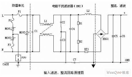
①Lightning protection circuitThe circuit composed of MOV1,MOV2,MOV3(F1、F2、F3、FDG1 ) protects the whole circuit when there is lightning and produced voltage leads in the power supply via power system.When the two terminals' voltgae of RPS is more than its work voltage ,its resistance magnitude drops to make high voltage energy consume on RPS.F1,F2,F3 will be burnt to protect next circuit if the current is excessive.②Input filter circuitDouble π type filtering network composed of C1,L1,C2 and C3 mainly prevents electromagnetic noises of input source and clutter signals to avoid the power supply being obstructed.Meanwhile,it also prevents that high frequency clutter generated by the power supply itself disturbs electrified wire netting. (View)
View full Circuit Diagram | Comments | Reading(507)
UC3842/UC3843 Isolation Single-end Flyback Switching Power Circuit
Published:2011/6/6 22:33:00 Author:Michel | Keyword: Isolation, Single-end, Flyback, Switching Power Circuit
Switching power supply has been widely used becauase of its advantages such as high efficiency, small volume. The traditional switch power supply uses voltage type pulse width modulation (PWM) technology, and recent years current-mode PWM technology has develpoed rapidly.Compared with voltage type PWM,current type PWM has better voltage and load adjustment rate.And the stability of system and dynamic characteristics also got significant improvement,especially its current-limiting and parallel current sharing ability make the control circuit simple and reliable.Current-mode PWM integrated controller has been industrialized,which pushes forward the small power switch power supply's development and application.Voltage-mode PWM controlling small power source has subsitituted current-mode PWM controlling small power power supply. (View)
View full Circuit Diagram | Comments | Reading(1990)
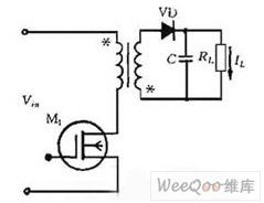
5V to 30V Booster Power Circuit of Gate Circuit
Published:2011/6/6 22:35:00 Author:Michel | Keyword: Gate Circuit, 5V to 30V, Booster Power Circuit
The 5V to 30V booster power circuit of gate circuit is showed as above. (View)
View full Circuit Diagram | Comments | Reading(944)
Principle and Circuit of Transformer Feedback Type Oscillator
Published:2011/6/10 7:27:00 Author:Michel | Keyword: Transformer, Feedback Type, Oscillator, Principle and Circuit
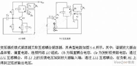
The transformer feedback oscillator is also called mutual-inductance coupling oscillator and it's typical circuit is showed as picture 5-6.The resonant amplifier is composed of transistor,bias circuit and frequency network.Cb is blocking couplingcapacitor,Ce is emittingbypass capacitor .It is coupled via L1L and the L1 feedback voltage is added to amplifier's input end.The sine wave output voltage obtained from load RL by L1L mutual-inductance coupling. (View)
View full Circuit Diagram | Comments | Reading(594)
Oscillator Circuit of Three - Point Capacitance
Published:2011/6/10 7:14:00 Author:Michel | Keyword: Three - Point Capacitance, Oscillator Circuit
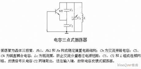
The oscillating tube is rystcal triode and Rb1,Rb2 and Re consititute stable bias circuit.Ce is AC shunt capacitor,itC3 and C4 is blocking coupling capacitor.Lc is choke which prevent the AC componet from passing through the power short-circuit.C1,C2 and L constitute frequency network.The feedback signals output from capcitance C2 and they are transmitted to input end,thus it is called capacitance feedback oscillator. (View)
View full Circuit Diagram | Comments | Reading(883)
Optically Coupled High-side Driving Circuit of Improved Double Power
Published:2011/6/10 6:55:00 Author:Michel | Keyword: Improved Double Power, Optically Coupled, High-side, Driving Circuit
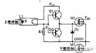
In the abboved double power coupling tube drive circuit scheme,using the copling output direct driving circuit makes the output waveform deformated seriously.Especially the falling edge of the waveform is slower, this is mainly caused by the capacitance between the MOS tube's G and S'level. The capacitance between G and s will be charged when the output waveform is high electricity ,which makes the wavefrom rise slightly slow.The capacitance between G and s will be discharged via R1 when the output waveform turns lower,which makes electric potential of MOS tube's G stage drop slowly and the wavform deformates seriously.It's impossible to remove the capacitance between G and s,we improve the mentioned driving project,according to pulling driving circuit on the thread on singlechip mouth and the imroving project is showed as above. (View)
View full Circuit Diagram | Comments | Reading(454)
Four-way Output Decoding Multiplex Converting Circuit of D-A Converter
Published:2011/6/10 4:52:00 Author:Michel | Keyword: D-A Converter, Four-way Output, Decoding, Multiplex Converting Circuit
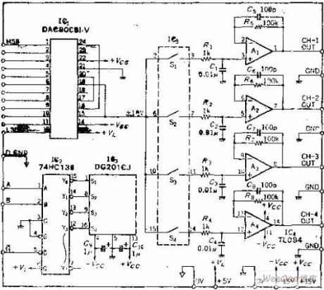
Circuit's Functions
Many A-D converters will be used when many analog switchers are connected to input ports,they are switching in multiplex ways and the channels' scanning are slow.This circuit is contrast,it changes a D-A converter into four ways output, constitutes four equivalent D-A converters,and it is used in the D-A output conversion speed slow circuit, which can reduce the cost.
Circuit's Work PrincipleAbout this circuit's work principle,it's easy to understand as long as you think of that 4 rotary switchs are connected to D-A converter's output port and the rotating shaft is whirling in high speed. (View)
View full Circuit Diagram | Comments | Reading(780)
555 FM Circuit
Published:2011/6/9 19:09:00 Author:Michel | Keyword: 555, FM Circuit

Cicuit's FunctionsThe frquency can be modulated once the charging current of 555 free-running multivibrator self- excited multivibrator ip-flop is altered.It's worth noting that it can be used as VCO if the charging current is greatly changed.This kind of oscillator's oscillation frequency is lower than 100 KHZ and the frequency of the circuit is 40 KHZ and it's close to infrared remote control frequency. This circuit also can be modulated as low frequency carrier frequency voice or data signal.
Circuit's Work PrincipleIf modulation frequency range is small, the leads 7 of the oscillating circuit can be connected to the resistance and it masses the blocking condenser stopping capacitor and then the FM moudulation can be constitituted (View)
View full Circuit Diagram | Comments | Reading(9)
Unijunction Transistor Constitutive Thyristor Trigger Circuit
Published:2011/6/4 22:12:00 Author:Michel | Keyword: Unijunction Transistor, Thyristor Trigger Circuit
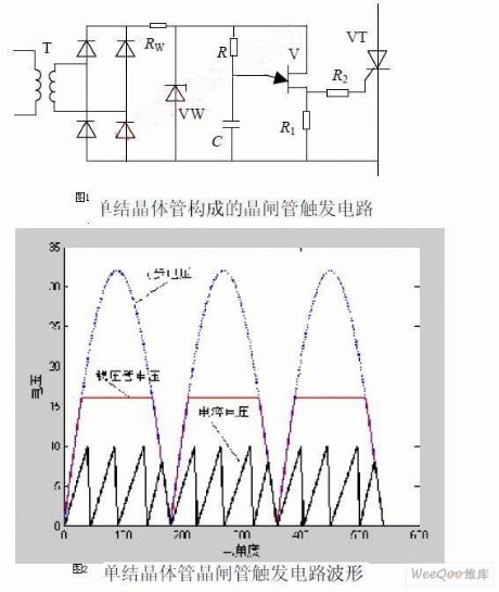
The thyristor trigger circuit composed of unijunction transistor is showed as the picture 1 and its voltage waveform is showed as the picture.Compared with relaxation oscillation circuit composed of unijunction transistor,the oscillating parts are same.Synchronous can be realized through improving power circuit.Sinusoidal alternating current bucks when it passes through the synchronous transformer T,changes into low ac voltage and then it changes into pulsing dc when it goes through diode rectifier bridge. The voltage regulator tube VW and resistor,RW's function is to clip and VW is off when pulsating voltage is lower than voltage regulator tube's voltage and both terminals' voltage is equal to rectifier output voltage. (View)
View full Circuit Diagram | Comments | Reading(790)
Circuit of Sawtooth Wave Generator with Constant Current Charging
Published:2011/6/4 1:31:00 Author:Michel | Keyword: Constant Current, Charging Sawtooth Wave Generator

Capacitor charging has almost nothing to do with collector voltage when the strong feedback transistor T is used.The required sawtooth wave amplitude can be gotten when R1 is changed.The collected current can be altered when R3 is changed to regulate frequency.Conversing capacitor value can change frequency in a wider range. (View)
View full Circuit Diagram | Comments | Reading(2284)
Trapezoidal Wave Generator Circuit
Published:2011/6/4 2:10:00 Author:Michel | Keyword: Trapezoidal, WaveGenerator Circuit
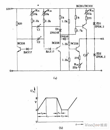
The trapezoidal wave generator showed as the picture(b) can be output when the picture (a) circuit is used.The trapezoidal wave's time t1 ~ t2 can be adjusted independently.Time T1 regulates via regulating capacitor C1 crudely,potentiometer fine respectivly.t2 is adjusted via regulating capacitor C2 crudely ,RP2 fine respectivly.t1+t2 fix the cycle or frequency.t3's change depends on potentiometer RP3 and its value is calculated as t3=CRE·UA/UE.Here RE is total PNP transistor shot extremel resistance, UE is emitter drop,UA is output voltage amplitude. (View)
View full Circuit Diagram | Comments | Reading(1600)
Triangle Wave - Rectangle Wave Generator Circuit
Published:2011/6/4 2:26:00 Author:Michel | Keyword: Triangle Wave, Rectangle Wave, Generator Circuit

This circuit is composed of three operational amplifiers and its frquency can be altered by changing resistence,R. (View)
View full Circuit Diagram | Comments | Reading(837)
Simple and Practical Motor Energy Braking Circuit
Published:2011/6/4 22:10:00 Author:Michel | Keyword: Motor, Energy Braking Circuit
The equipment driven by motor usually uses mechanical friction braking to accelerate parking and blasting vibration phenomenon may occur if the operation is inproper during the braking process.Hereby, some simple and practical motor energy braking circuit are for reference.The energy barking principle is :The two-phase stator winding connects to a DC power supply immediately after the stator winding goes off and then a static magnetic field generates in the stator winding.The rotor generates induction emf when it rotates in the magnetic field.The torque between rotor current and fixed magnetic blocks rotor's continous rolling,which generates barking effect and makes motor stalled quickly. (View)
View full Circuit Diagram | Comments | Reading(432)
| Pages:1761/2234 At 2017611762176317641765176617671768176917701771177217731774177517761777177817791780Under 20 |
Circuit Categories
power supply circuit
Amplifier Circuit
Basic Circuit
LED and Light Circuit
Sensor Circuit
Signal Processing
Electrical Equipment Circuit
Control Circuit
Remote Control Circuit
A/D-D/A Converter Circuit
Audio Circuit
Measuring and Test Circuit
Communication Circuit
Computer-Related Circuit
555 Circuit
Automotive Circuit
Repairing Circuit