
Circuit Diagram
Index 1765
Current Detection Circuit Diagram made up of LT1620 and Others
Published:2011/6/2 11:20:00 Author:leo | Keyword: Current Detection Circuit Diagram made up of LT1620 and Others, T1620

The picture shows a current detection circuit made up of LT1620 and so on. In this circuit, LT1620 is a integrated controller of voltage regulation power in the battery recharger. In the work mode, the LT1620 can produce load current signals under the +5V voltage.Itis madeup of a circuit with MOSFET(VT1) and other external devices to change the load current signals to output voltage based on the location. Therefore, the voltage can give a reflection of the change of load current I. (View)
View full Circuit Diagram | Comments | Reading(706)
Adjustable timing hige automatic switch circuit
Published:2011/6/8 6:46:00 Author:Fiona | Keyword: Adjustable timing hige automatic switch

Button switch AN11, AN2 is manual on and off. K11 and K22 is a separate automatic delay on and off. When connecting the power, the circuit charges to the C11 through the W11 and R11, when the voltage of the capacitor is above the peak of BG11, BG11 conducts to trigger the SCR conducts, the relay J is energized pick, J12 and J22 moves to control appliances. J11 closes to discharge the charge on the C11, BG11 closes. During the regular open, when SCR guides energy,point P is equivalent to grounding, often close point J12 is off, by the current charges to C21 through W21 and R21, when the voltage of C21 ends is higher than the peak of the BG21, BG21 conducts, the output signal makes SCR off by C5, the relay disconnects after losing the power, circuit resets.
(View)
View full Circuit Diagram | Comments | Reading(520)
Composed of one-way silicon controlled simple touch switch circuit
Published:2011/6/7 20:01:00 Author:Fiona | Keyword: Composed of one-way silicon controlled

Touch the metal piece to open, SCR1 turns on, the load is energized to work. Touch the metal piece off, SCR2 turns on, the relay J is energized to work,K is off, the load losses the power, SCR2 turns off, the capacitance discharges to the relay J, it keeps the relay pulling in about 4 seconds, so the circuit action is more accurate. If the load replays to the relay, it can control the large current work load. Friends who are interested, give it a try. (View)
View full Circuit Diagram | Comments | Reading(949)
The circuit diagram of amplifier made up of μA709
Published:2011/6/8 20:53:00 Author:leo | Keyword: The circuit diagram of amplifier made up of μA709 , A709

Picture 1 shows an amplifier made up ofμA709 and others. In this circuit, VT1 forms step attenuator which is regarded as a control part of automatically gaining. It is used to rectify and feedback the peak valve of its gate bias and connected to the negative feedback circuit of operating amplifierμA709.Feeback generated through R1 is used to make up nonlinear distortion of VT1. (View)
View full Circuit Diagram | Comments | Reading(694)
FR660-the integrated microcomputer circuit of communication single door
Published:2011/5/17 20:53:00 Author:Borg | Keyword: microcomputer, communication single door


GD9815-5 is an integrated microcomputer circuit of communication single door, which is used in wireless phones.1.function featuresFR660 contains sub-circuits of cell phone signal launch/receiving, ring control, charging detection, noise detection, generating of two-tone multiple-frequency DTMF signals, coding data signal generating, pulse dialing generating, out-layer series plugs and series communication plugs, with which we can detect dialing width and decodes, we can also use it to save the encoding information.
2.pin functions and data
(View)
View full Circuit Diagram | Comments | Reading(443)
Dual-watch controlled SCR timer circuit (3)
Published:2011/5/19 0:41:00 Author:TaoXi | Keyword: Dual-watch, SCR, timer circuit

Working principle: the circuit is as shown. When you press the K1, the power supply will be changed into the 6V DC after the proess of step-down, rectify and filtering. At this time, the power NC contact point J-3 makes J1 to work, and J1's normally open contact point J1-1 closes, the circuit will lock itself. At this time if you release K1, the circuit is in the working condition because of the self-locking. When the timing boot audio signal is input from the two ends of A, B, this signal will be rectified and filtered by D3 and C3 to trigger the SCR1 and makes J2 to work, J2's normally open contact point J-2 closes, socket W has the electricity, the controlled appliances is connected. Similarly, when another electronic alarm clock's regular shutdown audio signal is input from C and D, this this signal will be rectified and filtered by D5 and C4 to trigger the SCR2 and makes J3 to work.
(View)
View full Circuit Diagram | Comments | Reading(1504)
Composed of VMOS H bridge motor positive and negative drive circuit
Published:2011/6/7 19:48:00 Author:Fiona | Keyword: Composed of VMOS, H bridge motor, positive and negative drive
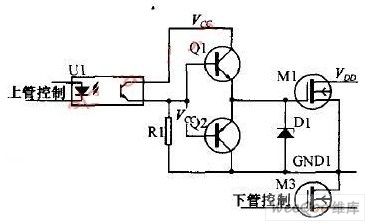
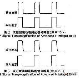
In the dual power optocoupler drive circuit scheme,use the output ofoptocoupler to direct-drive the MOS pipe, it would make the output waveform have a serious distortion,in particular the falling edge of the waveform is relatively slow, mainly caused by the capacitance between G and S of the MOS pipe. When the output waveform is high, charge to the capacitance between the G and S so that the wave increases slightly slow; when output waveform becomes low,the capacitance between G and S discharges through Rl to make the G of MOS pipe's potential decreasesvery slowly ,it leads to the the falling edge of the waveform has a serious distortion.
(View)
View full Circuit Diagram | Comments | Reading(793)
Double-watch timer circuit (1)
Published:2011/5/17 21:40:00 Author:TaoXi | Keyword: Double-watch, timer circuit

Related components PDF download:
9013
The circuit is as shown in the figure. This circuit uses two electronic wall watch with the alarm function, the signals is output from the both ends of piezoelectric ceramics. When the wall watch alarms, the signal gets to BG base port through C1 (or C2), and this signal is amplified to trigger the monostable circuit which is composed of the D flip-flop, Q1 outputs the high-level voltage and triggers the bistable circuit which is composed of the D flip-flop, Q2 outputs the high-level voltage and triggers the SCR to turn on; Meanwhile the LED lights, the Instruction timer is working. The monostable circuit's Q1 outputs the high-level voltage to charge C4 through R3, after a certain time, R1 has the high-level voltage to make Q1 to restore the low level. When the second watch alarm, the monostable circuit outputs a positive pulse to make the bistable circuit to output the low level voltage, so the LED turns off, the electrical equipments are out of electricity.
(View)
View full Circuit Diagram | Comments | Reading(766)
BA6029,BA6209N,BA6209U,BA6209V-The speed-stable circuits of TV sets
Published:2011/5/17 22:27:00 Author:Borg | Keyword: speed-stable circuits, TV sets


BA6029,BA6209N、BA6209U、BA6209V are speed-stable circuits of TV sets, which are produced by Toyo Corp.,Japan. It is used to drive tape motors, principle motors and tape winding motors, ordering them to stop or wind/rewind. All the internal circuits and typical application circuits of these integrated circuits are almost the same, except for the few differences in packages and parameters. The following is BA6209 as a example.1.The internal circuit and pin functions of BA6209BA6209 can drive motors directly and afford the curren of 1.5A.
(View)
View full Circuit Diagram | Comments | Reading(2810)
BA6235F-The stable integrated circuit of D.C motors
Published:2011/5/17 20:49:00 Author:Borg | Keyword: integrated circuit D.C, motors


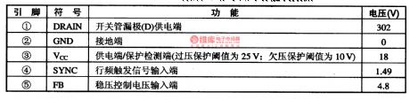
BA6235F a stable integrated circuit of D.C motors produced by Toyo Corp.,Japan, which is always used in Walk-man and radios.1.the typical application circuit of BA6235FThe application circuit of BA6235F chips is as shown in Figure 1.
2.pin functions and data of BA6235F BA6235F is a stable integrated circuit of D.C motors, which is in flat 8-lead dual-line package, and its pin functions and data is listed in Table 1.
3.notes for fault detecting and repairing If we want to judge whether BA6235F is malfunctioning, we can test the values of pinning voltages and compare them with common values. (View)
View full Circuit Diagram | Comments | Reading(574)
SCR over-current protection circuit with the Hall components
Published:2011/5/17 22:03:00 Author:TaoXi | Keyword: SCR, over-current protection, Hall components


Related components PDF download:
ULN302067L070
Here we introduce one kind of SCR over-current protection circuit that uses the Hall components as the sensor, it has the overheat protection function and the sound and light alarm function. The principle circuit is as shown in figure 1.
The IC1 and IC2 are the Hall integrated circuit ULN3020, in the normal operation, their output port pins always have the low level voltage, D2 and D3 close, the SCR T1 is in the shutdown state, LED L4 does not light, the positive power supply form a loop through the R6, L1, IC4, R5, VT and the ground, if the base port of the control switch transistor VT has the high level voltage, it is in the conduction-status to open the zero-crossing trigger IC4 and also to trigger the two-way silicon T3, the load RL gets the power to work, their current will generate an alternating magnetic field in the magnetic circuit, if the peak value of the magnetic field intensity does not reach the two hall components' opening magnetic field strength, IC1 and IC2 will be maintained the original state. (View)
View full Circuit Diagram | Comments | Reading(789)
Low cost high precision automatic shift proportion amp circuit
Published:2011/6/7 3:37:00 Author:Fiona | Keyword: Low cost high precision, automatic shift proportion amp

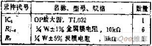
In addition to R5, the other resistance is best to be carefully selected, has the same parameters,2 20K precision resistor in series can be instead of R4.It can increase the control gain range to increase the number of CD4066 and R7. Remove the comparator, It can directly control gain by the MCU. The circuit can be widely used in expansion A / D accuracy, detection range extension and so on. (View)
View full Circuit Diagram | Comments | Reading(466)
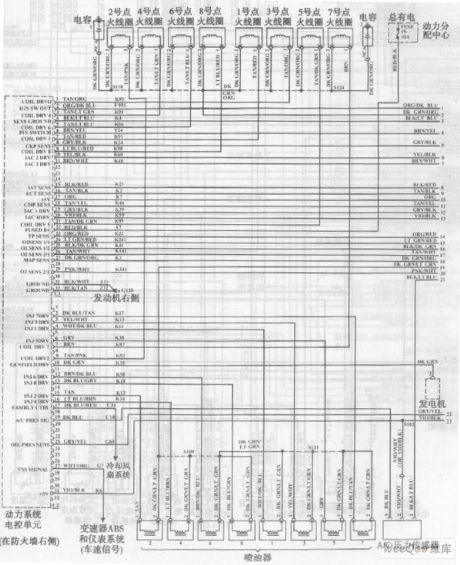
Beijing daqienuoji automobile engine circuit
Published:2011/6/7 3:39:00 Author:Fiona | Keyword: Beijing daqienuoji automobile engine
View full Circuit Diagram | Comments | Reading(523)
FAN8200,FAN820OD--a motor driven integrated circuit
Published:2011/5/18 2:51:00 Author:Borg | Keyword: stepper, motor driven, integrated circuit
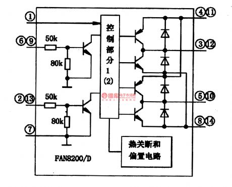

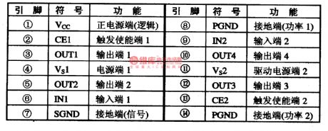
FA820OD and FAN8200D are a kind of integrated circuit of low voltage single door and stepper motors, which can be used in two-phase stepper motor driven systems of digital cameras, disc drivers, safety mobile control and thermal printers.1.function featuresFAN820O and FAN820OD consist of two identical control circuits. The control signals come in from IN point, and into internal controllers after backing-buffered, then they are handled by the control part and drive the NPN, finally, they come out from OUT point as the form of square waves and make the motor run.
2.pin functions
(View)
View full Circuit Diagram | Comments | Reading(460)
Magnification is 2 small vary the unbalanced output circuit
Published:2011/6/3 21:56:00 Author:Fiona | Keyword: Magnification is 2 , small vary the unbalanced output
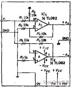
Circuit Work
Mention of the balanced output, people tend to immediately think of adding OP amplifier at the output of the positive-phase amplifier to be the inverting amplifier circuit, inverting the normal phase and the invert phase make up the balanced output. In the DC circuit, although this method can be used, but if it is broadband signal, phase shift of inverting amplifier is a problem. The drift of the OP amplifier A1 and A2 is equal in this circuit, so even if the input frequency changes,it won't happen phase distortion.
(View)
View full Circuit Diagram | Comments | Reading(383)
BA6191-the 2-channel bilateral-control integrated circuit of motor drive
Published:2011/5/17 22:29:00 Author:Borg | Keyword: 2-channel, bilateral-control


BA6191 is a 2-channel bilateral-control integrated circuit of motor drive produced by Toyo Corp., which is often used in VCD, SVCD and CVD single/multipleplayers as motor drives. 1.the internal circuit BA6191 contains logic control circuit and drive circuit, whose internal circuit is as shown in Figure 1.
2.pin functionsBA6191 is in 12-lead single in-line package, whose pin functions and data are listed in Table 1. (View)
View full Circuit Diagram | Comments | Reading(729)
BA5902FP-laser head servo-driven integrated circuit
Published:2011/5/18 22:13:00 Author:Borg | Keyword: laser head, servo-driven


BA6196FP is a motor-driven integrated circuit produced by Toyo Corp., which is used in laser heads to laser players.1.The internal circuitBA6196FP contains 4-channel BTL drive circuit and drive silence-noise control circuit, whose internal circuit is shown in Figure 1.
Figure 1 the internal circuit of BA5902FP
pin functions BA5902FP is in 28-lead dual in-line package, whose pin functions are listed in Table 1.
Table 1 pin functions and data of BA5902FP chips (View)
View full Circuit Diagram | Comments | Reading(563)
The fault detection circuit of Santana AJR engine
Published:2011/6/10 3:22:00 Author:Borg | Keyword: fault detection circuit, Santana
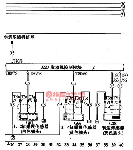
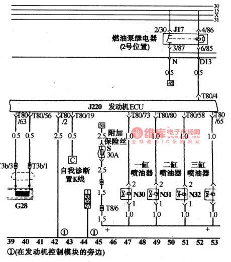
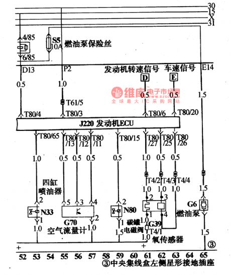
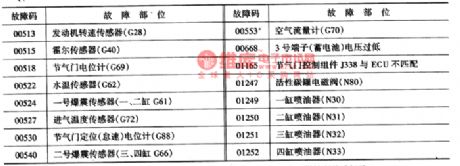
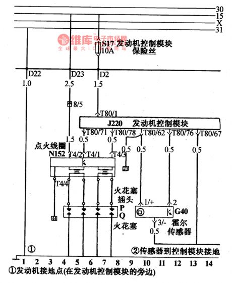
The computer J220 of the AJR engine can save the fault of sensors and executing components, and the fault codes have to be read out by VAG1552 or VAG1551 fault detectors or other multiple code readers which are produced by Volkswagon AG. The figure and instructions of VAG1551 fault detector have been narrated in the power jet circuit of Santana 20OOGLi. VAG1552 is up-grated on the basis of VAG1551, and the size is smaller, functions are more complete, the figure of it is like a laptop.
(View)
View full Circuit Diagram | Comments | Reading(518)
BA3521-the integrated circuit of stereo reproducing single door
Published:2011/6/10 3:23:00 Author:Borg | Keyword: integrated circuit, single door


EM78811 is an integrated circuit of stereo reproducing single door, which is widely used in walk-man and portable radios.1.The internal circuit and pin functions of BA3521BA3521 contains 2-channel pre-stage, 2-channel headphone power amplifier, power volume control circuit and mute circuit while power supply is on. The internal circuit of is as shown in Figure 1. It is in 18-lead dual in-line package, whose pin functions are listed in Table 1.
2.Main parameters of BA35213.The typical application circuit of BA3521
(View)
View full Circuit Diagram | Comments | Reading(1042)
The relay and fuse circuit on the top of Santana central connection box
Published:2011/5/18 22:16:00 Author:Borg | Keyword: relay, fuse, central connection box, Santana

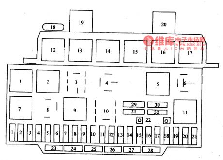
The central connection box is the connecting linchpin of the whole car, which is at the acetabulum under the instrument plate. There are more than 20 relays and more than 30 fuses fixed on the surface of the box, while more than 10 connectors on the ground of it. The inside surface is an insulated PVC box inlaid with copper bars of layers, separated or linked, which formthemainstream circuit centralized with igniting switches, and connectors are linked with the front and rear part of the car and instrument bundles respectively. The positions of relays and fuses are shown in Figure 2-1(notes: chassis No. is 32MP003182).
(View)
View full Circuit Diagram | Comments | Reading(532)
| Pages:1765/2234 At 2017611762176317641765176617671768176917701771177217731774177517761777177817791780Under 20 |
Circuit Categories
power supply circuit
Amplifier Circuit
Basic Circuit
LED and Light Circuit
Sensor Circuit
Signal Processing
Electrical Equipment Circuit
Control Circuit
Remote Control Circuit
A/D-D/A Converter Circuit
Audio Circuit
Measuring and Test Circuit
Communication Circuit
Computer-Related Circuit
555 Circuit
Automotive Circuit
Repairing Circuit