
Circuit Diagram
Index 1752
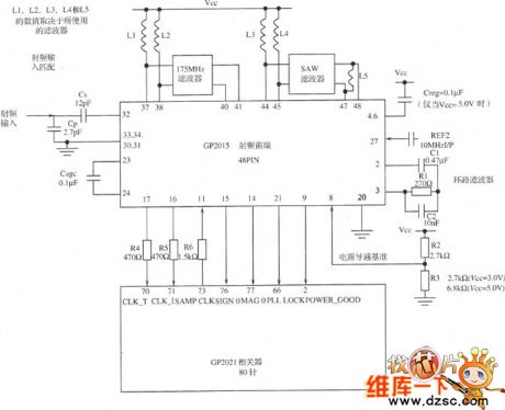
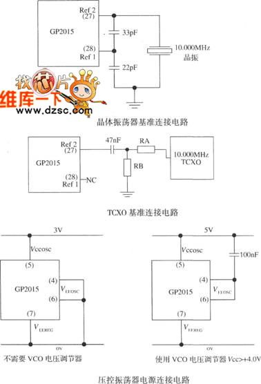
The GPS receiver RF circuit of GP2015
Published:2011/6/13 22:05:00 Author:Seven | Keyword: GPS receiver, RF circuit
View full Circuit Diagram | Comments | Reading(586)
The PLL FM modem circuit
Published:2011/6/13 22:02:00 Author:Seven | Keyword: PLL, FM modem

View full Circuit Diagram | Comments | Reading(2515)
3.1 the amplifier circuit
Published:2011/6/15 3:32:00 Author:Borg | Keyword: amplifier circuit

In figure 4 is the amplifier circuit in the signal adjusting circuit, which is a passive feedback amplifier circuit composed of the computing amplifier, and the amplified times of the output signals can be further trimmed by adjusting the adjustable resistor RW2. The output signal subtracts 0g LEV, which can make the output voltage value of the amplifier be 1/10 of the acceleration, so it is more convenient to indicate the number. By adjusting the resistance of RW2, the 0g LEV can be trimmed, and the signal bias can be modified. In the figure, VSS is a power supply of -5V, VCC is a +5V power supply.
(View)
View full Circuit Diagram | Comments | Reading(846)
The passive power supply generator consisting of NAND
Published:2011/6/15 7:34:00 Author:Borg | Keyword: power supply generator, NAND

In the electric instrument, there often needs a team of low-power passive power supplies, which can be assembled with 3 NAND in the figured way, then the power supply polarity can be changed quickly. The the circuit, A1 and A2 form a self-motivated multi-resonance oscillator whose frequency is about 4KHz, A3 is the buffer which is also the rectifier. When the oscillating circuit A3 is outputting a high LEV, VDI is conducting, C2 is charged, A is positive and B is passive, VD2 is blocked. When A3 is outputting a low LEV, as the voltage on the two poles of C2 can't mutate quickly, so the 8 points are in a passive voltage. (View)
View full Circuit Diagram | Comments | Reading(704)
The frequency doubler of 50% duty cycle (555)
Published:2011/6/15 2:54:00 Author:Borg | Keyword: frequency doubler, duty cycle

View full Circuit Diagram | Comments | Reading(1954)
The absolute value detection circuit
Published:2011/6/15 2:43:00 Author:Borg | Keyword: absolute value, detection
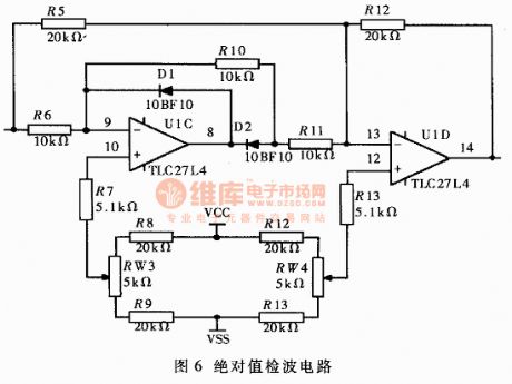
By the absolute value detection circuit (see as figure 6), we can settle the absolute values of the communication signals, which is convenient for the indication of the acceleration value. when the input signal Vin>0, the output signal Vout=Vin; but when Vin<0, Vout=-Vin.
Figure 6. The absolute value detection circuit (View)
View full Circuit Diagram | Comments | Reading(932)
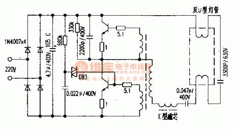
The electric ballast circuit of 3300P/630V
Published:2011/6/15 2:35:00 Author:Borg | Keyword: electric ballast
View full Circuit Diagram | Comments | Reading(608)
The simple mixing and surround sound generator
Published:2011/6/15 2:45:00 Author:Borg | Keyword: mixing, surround sound

View full Circuit Diagram | Comments | Reading(2193)
The dual-way video amplifier circuit composed of MAX457CPA
Published:2011/6/15 3:17:00 Author:Borg | Keyword: video amplifier, dual-way

View full Circuit Diagram | Comments | Reading(591)
Haier FCD-40A horizontal electric water heater circuit
Published:2011/6/14 3:02:00 Author:Christina | Keyword: Haier, horizontal, electric water heater
Haier FCD-40A horizontal electric water heater circuit
(View)
View full Circuit Diagram | Comments | Reading(617)
51 monolithic burning device circuit
Published:2011/6/14 3:02:00 Author:Christina | Keyword: monolithic, burning device
51 monolithic burning device circuit
(View)
View full Circuit Diagram | Comments | Reading(446)
M15M machine core protection circuit
Published:2011/6/12 22:47:00 Author:Christina | Keyword: machine core, protection circuit
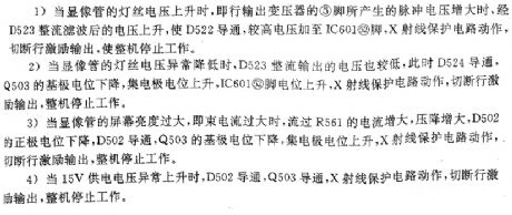
The M15M machine core protection circuit is as shown:
1.When the voltage of the CRT's filament increases, the voltage which is rectified and filted by the D523 increases too, the D522 conducts, the high voltage adds to pin-2 of the IC601, the X-ray protection circuit starts working to cut off the line excitation output, the device stops working.
2.When the voltage of the CRT's filament decreases, the the voltage which is rectified and filted by the D523 decreases too, at this time the D524 conducts, the base port potential of the Q503 decreases, the collector potential increases, the voltage of IC601's pin-52 increases, and the X-ray protection circuit starts working to cut off the line excitation output, the device stops working.
3.When the CRT's brightness is too large, the device stops working.
4.When the 15V power supply voltage increases, the device stops working. (View)
View full Circuit Diagram | Comments | Reading(435)
interface circuits of the MAX110/MAX111 and the SCM
Published:2011/6/13 4:21:00 Author:Christina | Keyword: SCM, interface circuit

View full Circuit Diagram | Comments | Reading(525)
interface circuits of the MAX187/189 and 8031
Published:2011/6/13 4:20:00 Author:Christina | Keyword: interface circuit

View full Circuit Diagram | Comments | Reading(595)
Voice type logic pen circuit (CD4011) composed of the gate circuit
Published:2011/6/12 22:26:00 Author:Christina | Keyword: Voice type, logic pen, gate circuit
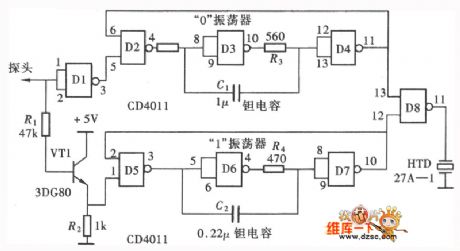
The test result of the shining type logic pen need to be observed by the eyes. Due to the high development of the modern electronic production technology, the soldered dots of the circuit board are very intensive. So you must concentrate on the measure point when you are testing. We make a voice tester, so that our ears can also be used in the testing, this method will greatly improves the testing efficiency. The voice type logic pen which is composed of the NAND gate is as shown in the figure.
(View)
View full Circuit Diagram | Comments | Reading(463)
Electricity-saving voltage stabilizer circuit
Published:2011/6/12 22:28:00 Author:Christina | Keyword: Electricity-saving, voltage stabilizer
The electricity-saving voltage stabilizer circuit is as shown in the figure. This voltage stabilizer has the function of general delay stabilizer, the features are:(1)when the city electricity voltage is in the range of the safe voltage 220V±10%, the voltage stabilizer automaticly cuts off the power to add the city electricity to the load directly, this eliminates the power consumption of the voltage stabilizer. (2)when the city electricity voltage exceeds the safety voltage range, it will increase or decrease the voltage automatically. (3)when the load is zero, the voltage stabilizer automatically cuts off the power to eliminate the power consumption of the no-load. (4)when the input voltage is 160V to 270V, the output voltage is in the range of 220V±10%, the conforms to the state standards. The power is 2500W.
(View)
View full Circuit Diagram | Comments | Reading(4128)
Multi-function telephone control switch circuit
Published:2011/6/12 22:28:00 Author:Christina | Keyword: Multi-function, telephone, control, switch

The function of this machine is as follow:
(1)Remote control, local control: the operator can call the telephone which is in parallel with this control through the external, when the number of phone rings is equal to the value of the controller setting, the controller will automatically simulate the off-hook and send out the long beep of Di to remind the operator to input the password.
(2)Off-electrical memory protection
(3)Query function: you can query the opening and closing state of the switch
(4)Automatically hangs up
Components selection: the audions VQ4 and VQ5 can use the 9014. The VD5 and VD6 can use the 5mm red light-emitting diode. The resistance of R20 is 100Ω, the resistance of R19 is 47Ω, the resistance of R18 is 100Ω. The other components is as shown in the figure. (View)
View full Circuit Diagram | Comments | Reading(1360)
The over-voltage protection circuit (1)
Published:2011/6/14 2:42:00 Author:Christina | Keyword: Over-voltage, protection

The over-voltage protection circuit is as shown in the figure. This circuit uses the photoelectric coupler's on-off to control the device. When the voltage is normal, the photoelectric coupler has no output, the VT tube cuts off because of the reverse bias. When some reasons increase the voltage of this circuit, the voltage of the sampling circuit subprime stage will increase too, the photoelectric coupler meets the working condition. The light-coupler output current increases the VT tube's bias voltage and make the VT tube to conduct, the actuator's relay closes and cuts off the power supply to protect the electrical equipment. If the fault is eliminated, the voltage will be normal, this circuit will immediately quit the working condition to recover the power supply of the circuit. (View)
View full Circuit Diagram | Comments | Reading(566)
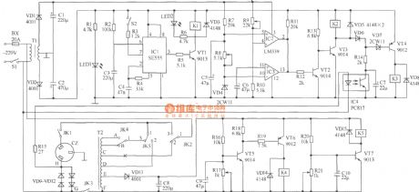
using DH-03C pyroelectric infrared to control delay spotlight circuit
Published:2011/5/19 7:22:00 Author:Lena | Keyword: pyroelectric infrared , delay, spotlight

(View)
View full Circuit Diagram | Comments | Reading(347)
The temperature control circuit
Published:2011/6/13 22:23:00 Author:Christina | Keyword: Temperature, control

The temperature control circuit is as shown in the figure. This circuit is composed of the capacitance step-down circuit, the bridge rectifier circuit and the diode voltage regulator circuit. The diode voltage regulator circuit supplies the operating voltage for the temperature control thyristor, the control circuit is composed of the relay. The value of capacitor C1 can be selected by the size of the relay operating current, the zener VD5 should be determined according to the relay's operating voltage.
Figure: The temperature control circuit (View)
View full Circuit Diagram | Comments | Reading(680)
| Pages:1752/2234 At 2017411742174317441745174617471748174917501751175217531754175517561757175817591760Under 20 |
Circuit Categories
power supply circuit
Amplifier Circuit
Basic Circuit
LED and Light Circuit
Sensor Circuit
Signal Processing
Electrical Equipment Circuit
Control Circuit
Remote Control Circuit
A/D-D/A Converter Circuit
Audio Circuit
Measuring and Test Circuit
Communication Circuit
Computer-Related Circuit
555 Circuit
Automotive Circuit
Repairing Circuit