
Circuit Diagram
Index 1754
Hearing-aid (the 4th)
Published:2011/6/6 5:07:00 Author:Felicity | Keyword: Hearing-aid (the 4th)
Work of the circuit
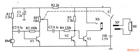
The hearing-aid circuit consists of power circuit, volume amplifier circuit and amplifying output circuit. (It is showed in picture 9-80.).
Turn on the switch S and GB supplied 1,5V voltage to the circuit. BM turns the sound signal it collects into electric signal which drives BE to make sound after being adjusted by V1,V2 and V3.
If you change the value of RP you can change the volume. (View)
View full Circuit Diagram | Comments | Reading(2643)
Hearing-aid (the 3rd)
Published:2011/6/6 5:09:00 Author:Felicity | Keyword: Hearing-aid (the 3rd)
Work of the circuit
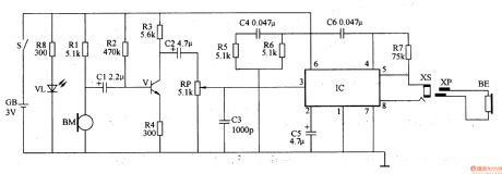
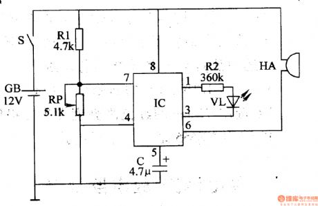
The hearing-aid circuit consists of volume amplifier circuit, capacity amplifier circuit and power indicating circuit (It is showed in picture 9-79.).
Turn on the power switch S and VL is lightened. In the same time volume amplifier circuit and capacity amplifier circuit begin to work. BM collects sound signalandthen turnsitinto faint electric signal which drives BE to make sound after being adjusted by V, RP and IC. When GB is lack of power light of VL will become faint to remind the users to change the battery. (View)
View full Circuit Diagram | Comments | Reading(2907)
Bell of the Bicycle (the 4th)
Published:2011/6/6 5:12:00 Author:Felicity | Keyword: Bell of the Bicycle (the 4th)

Work of the circuit
The circuit consists of LPO amplifying outputting circuit (transistor V1,V2, potentiometer RP, resistor R1-R4 and capacitor C) and power circuit (It is showed in picture 7-170.).
Press control button S and LPO begins to work. The signalwhich isproduced by LPOdrives HA to make sound “tick” after being amplified by V3.
Change the value of RP or C to change the volume. (View)
View full Circuit Diagram | Comments | Reading(578)
Hearing-aid (the 2nd)
Published:2011/6/6 5:14:00 Author:Felicity | Keyword: Hearing-aid (the 2nd),

Work of the circuit
The hearing-aid circuit consists of mike BM, resistor R1 and R2, capacitor C1-C4, potentiometer RP, integrated circuit, power switch S and earphone BE. (It is showed in picture 9-78.).
BM collects the sound signal andturns itinto faint electric signal. Then the signal is inputted from IC’s pin 7 through CI and RP. At last it is returned to sound by earphone after being amplifier.
If you change the value of RP you can change the volume. (View)
View full Circuit Diagram | Comments | Reading(1625)
Bell of the Bicycle (the 3rd)
Published:2011/6/6 5:17:00 Author:Felicity | Keyword: Bell of the Bicycle (the 3rd)
Work of the circuit
The circuit consists of audio frequency oscillator, LFO and voice outputting circuit (It is showed in picture 7-169.).
When you press button S and LFO starts to work and VL shines. In the meantime audio frequency oscillator is modulated. The modulating pulse signal which is outputted from IC’s pin 3 drives BL to make the sound “honk honk”. (View)
View full Circuit Diagram | Comments | Reading(508)
Bell of the Bicycle (the 1st)
Published:2011/6/6 5:27:00 Author:Felicity | Keyword: Bell of the Bicycle (the 1st)

Work of the circuit
The circuit consists of monostable trigger and voice circuit. (It is showed in picture 7-167.).
When you turn on the power switch Sthemonostable trigger is in the stable condition. Loudspeaker BL makes no sound.
When our hand touches pole A the body inducted signal is supplied to IC1’s pin 2 through C1. In this situation loudspeaker BL makes sound. (View)
View full Circuit Diagram | Comments | Reading(554)
M50436—500SP(TV) infrared remote control reception microprocessor circuit
Published:2011/5/26 8:52:00 Author:Lena | Keyword: infrared, remote control, reception, microprocessor
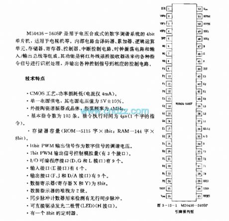


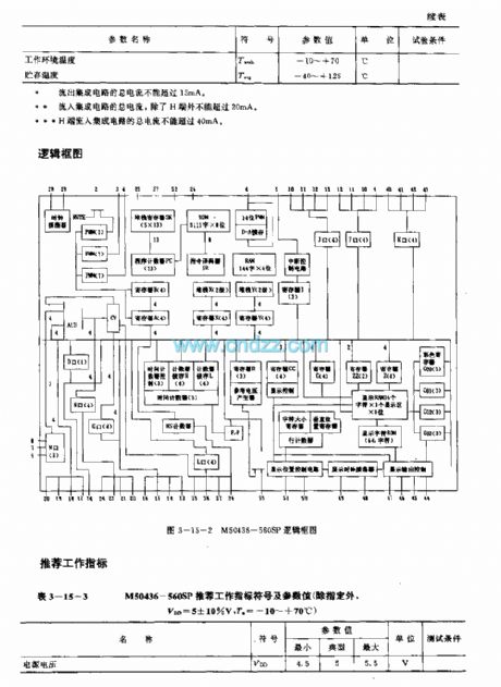
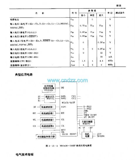
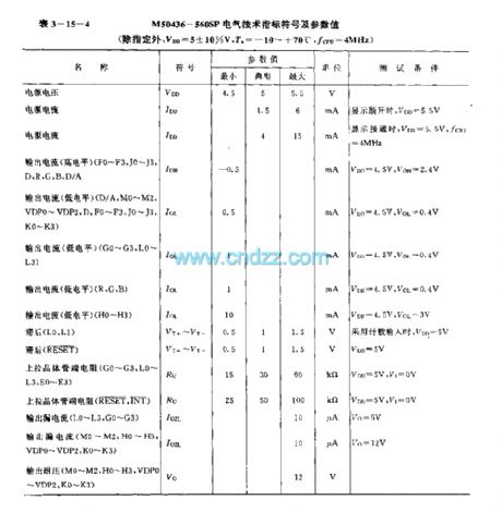
M50436-560SP are 4bit singlechips used in voltage synthesized digit tune system, applied to TV etc. Internal circuit consists of encoder, accumulator, logic operation unit, storage, register, controller, cut-off control circuit, clock oscillating circuit and input/output bus line etc. Identifing different instruction signals sentfrom infrared remote control receiver, then the circuit outputs control signals to control circuit.
technology features
CMOS technics, power loss is low(The current is only 4mA)
(View)
View full Circuit Diagram | Comments | Reading(1025)
Eye-care Lamps (the 7th)
Published:2011/6/6 5:22:00 Author:Felicity | Keyword: Eye-care Lamps (the 7th)

Work of the circuit
The circuit consists of light examine circuit and light adjusting circuit (It is showed in picture 9-74.).
When you turn on power switch the 220V AC voltage produces 2.2-2.4V DC voltage in CI. When the lamp light is weak the red diode is lightened. When the lamp light is strong enough the green diode is lightened.
You can change the value of RP2 to change the light intensity of the lamp. (View)
View full Circuit Diagram | Comments | Reading(673)
Eye-care Lamps (the 4th)
Published:2011/6/6 5:25:00 Author:Felicity | Keyword: Eye-care Lamps (the 4th)
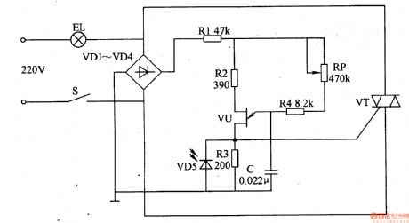
Work of the circuit
The circuit consists of power switch S, rectifier diode V1-V4, resistor R1-R3, light-sensitive diode VD5 and light EL (It is showed in picture 9-71.).
When you turn on the power switch S the 220V AC voltage is limited and reduced by EL. The voltage separates into two parts. One is supplied to the poles of VT while the other one supplies DC voltage to relaxation OSC and makes EL work. When the environmental light is strong light of ELbecomes weak. When the environmental light is weak the light of ELbecomes strong.
Change the value of RPand you canmake the change smoothly without shining. (View)
View full Circuit Diagram | Comments | Reading(434)
Current Amplifier Circuit Diagram made up of LF356 and Others
Published:2011/6/14 19:24:00 Author:leo | Keyword: Current Amplifier Circuit Diagram, LF356
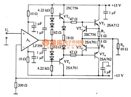
What the picture 1 shows is a current amplifier circuit made up of LF356 and so on. In the circuit, A1 is the backing amplifier while VT1 and VT2 (VT3 and VT4) can made up of the dual push-pull emitter follower circuit which amplifies DC signals with the frequency of 30 KHz and its output power is 1W. Vt5 and VT6 is used to protect power transistor when output circuit shorts. R1 is the sample and when the emitting polar current of VT3 and VT4 is 0.6A with the VT5 and VT6 on, VT5 and VT6 force the VT3 or VT4 to lower the base electric potential to protect the power transistor VT3 or VT4. (View)
View full Circuit Diagram | Comments | Reading(3325)
Eyesight Protecter (the 3rd)
Published:2011/6/6 5:21:00 Author:Felicity | Keyword: Eyesight Protecter (the 3rd)
Work of the circuit
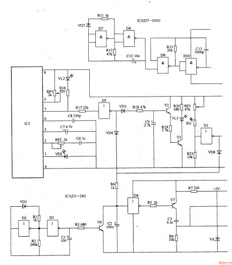
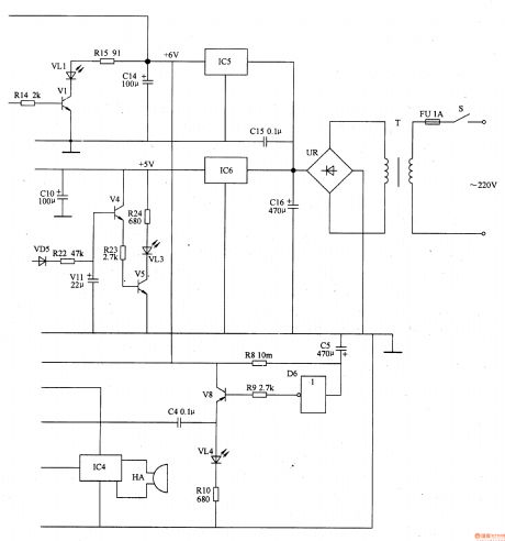
The circuit consists of power circuit, infrared launching circuit, infrared reception and amplifying circuit, light examining circuit, zero clearing pulse circuit, timing controlling circuit and acousto-optic warning circuit (It is showed in picture 9-61.).
Turn on the switch and the 220V AC voltage supplies the working power to the whole circuit after being adjusted. When the user’s head is too near from the writing pad (the distance is less than 35cm) VL2 shines and HA makes the sound “tick tick” to alarm the user. When the environment light is strong enough the voltage of VD is not so high. Here VL does not shine and HA makes no sound. When the environment light is dim the voltage of VD is high. Here VL shines and HA makes the sound “tick tick”. When the regular time is over VL3 is lightened and the HA makes sound to remind the user to have a rest. Also only if the user’s head is too near from the pad for more than 5s does the warming work. (View)
View full Circuit Diagram | Comments | Reading(447)
Voice Compression Circuit Diagram formed by MC1590 and Others
Published:2011/6/14 20:48:00 Author:leo | Keyword: Voice Compression Circuit Diagram formed by MC1590 and Others, MC1590

View full Circuit Diagram | Comments | Reading(3318)
Inverting Proportional Amplifier Circuit Diagram
Published:2011/5/18 8:50:00 Author:Felicity | Keyword: Inverting Proportional Amplifier Circuit,

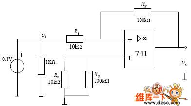
(View)
View full Circuit Diagram | Comments | Reading(525)
Storage Battery Voltage Monitor (2)
Published:2011/5/16 4:47:00 Author:Sue | Keyword: Storage, Battery, Voltage, Monitor
Here we will introduce a storage battery voltagle monitor circuit composed of digital integrated circuit CD4011. The drivers can know whether the battery voltage is proper by observing the lights on the monitor. When the voltage is proper, the light doesn't work. When the voltage exceeds a certain value, the light will keep on working. When the voltage is reduced to a certain value, the lightwill betwinkling, warning the driver of the low voltage which need charging.
Working Principle:
As seen in the figure 7-49, the storage battery monitor circuit consists of four-NOT gate integrated circuit IC's 2 inside NOT gate circuit D1,D2 and resistor R1-R5, potentiometer RP1,RP2, capacitor C, transistor V, indicating light HL.
When the voltage is proper, IC's 4 pin outputs low level, and V is disconnected, HL doesn't work.
When the voltage is higher than the proper one, IC's 4 pin outputs low level, and V is connected, HLkeeps on working.
When the voltage is lower than the proper one, IC's4 pin outputssquare form pulse, and V is connected and disconnected from time to time, HL keeps twinkling. (View)
View full Circuit Diagram | Comments | Reading(666)
Close-door Reminder
Published:2011/5/12 3:06:00 Author:Sue | Keyword: Close-door Reminder

The close-door reminder can send out the sound Please close the door. when one goes in or out of the room, and the sound will stop when the door is closed. It can also be used in places like confidential room, reference room, office and so on.
Working principle:
As seen in the figure 6-223, the reminder circuit is composed of power circuit, sound generator and power amplifying circuit.
The power circuit consists of battery GB, door contact switch S, current-limiting resistor R2, zener diode vs and filter capacitor C1,C6.
The sound generator consists of speech integrated circuit IC1, resistor R1,R3 and capacitor C2.
The power amplifying circuit consists of audio power amplifying integrated circuit IC2, capacitor C3-C5, resistor R4 and loudspeaker BL.
When the door is closed, S is disconnected, so the whole circuit isn't working. When the door is opened, S is connected, IC1 receives a voltage of +3V and begins to work. Its OUT terminal outputs sound signal, which will promote BL to make out the sound of Please close the door after being amplified by IC2.
When the door is closed, S is disconnected, and the whole circuit stops working.
Choices of components: R1,R2,R4:1/4W or 1/8W carbon film resistor. R2:1/2W carbon film resistor.
C1,C3-C6:aluminium electrolytic capacitor with a durable pressure of 16V. C2:monolithic ceramic capacitor or dacron capacitor.
VS:1/2W, 3V silicon voltage stabilizing diode.
IC1: Sound integrated circuit with saved signal of Please close the door. , such as HFC5203A. IC2:LM386N audio power amplifying integrated circuit.
BL: 0.5-1W, 8Ω electronic loudspeaker.
S:stroke switch. (View)
View full Circuit Diagram | Comments | Reading(1091)
Infrared Ray Detection Alarm
Published:2011/5/16 4:46:00 Author:Sue | Keyword: Infrared Ray, Detection, Alarm

When S1 is connected, infrared ray emission circuit begins to workwith a certain frequency, and outputs infrared ray pulse through VL2-VL4. When VL has no objects in from of it, IC's 6 pin outputs no signal.
When VL has objects in front of it within 1.5m, infrared ray signals emitted by VL2-VL4 will be absorbed by VL1 after reflection. VL1 will turn the ray signal into electric signal, and send it into IC to amplify signal. The electric signal after being amplified by IC will make the audio oscillator begin to work and promote the loudspeaker BL to make a warning sound. (View)
View full Circuit Diagram | Comments | Reading(479)
Seating Position Reminder(1)
Published:2011/5/12 3:02:00 Author:Sue | Keyword: Seating Position, Reminder

Unproper sitting position can do harm to children's eyesight and health. Now the introduced sitting position reminder can make a sound of di di or language reminding sound to remind the users of proper sitting postion.
Working Principle:
As seen in the figure 6-212, the reminder consists of electronic switch circuit GB, warning circuit and power circuit.
The electronic switch circuit consists of glass mercurial switchS2, transistor V1,V2 and resistor R1-R3.
The power circuit consists of power GB and switch S1.
When S1 is connected, GB offers the whole circuit voltage.
When the user's sitting position is proper, S2 is disconnected and the whole circuit doesn't work.
When the user's sitting position isn't proper(the distance bewteen the user and the dest is closer), S2 is connected and V1,V2 are connected. V2 generates a high voltage to IC's TRIG terminal, making IC begin to work. The OUT terminal will output audio signal which will make the di di warning sound or reminding sound of Please adjust your sitting position to avoid myopia after is is amplified by V3.
Choices of Components:
R1-R3:1/4W or 1/8W carbon film resistor.
V1,V3:S9013 or 3DGl2 silicon NPN transistor; V2: S9012 or 3CG2l silicon PNP transistor.
IC:HFC9301 exclusive integrated circuit with saved di di sound or KD56028 sound integrated circuit with saved sound of Please adjust your sitting position to avoid myopia.
S1: Miniture toggle switch; S2: KG series glass mercurial switch.
BL:8Ω、O·25W electronic loudspeaker.
GB:Two 1.5V size 5 dry batteries. (View)
View full Circuit Diagram | Comments | Reading(843)
Smoking Warning Indicator (3)
Published:2011/5/20 3:36:00 Author:Sue | Keyword: Smoking, Warning, Indicator

When the gas sensor detects no smoke, V1's breakover ability is weak because of lack of VL's infrared light. V2 then is disconnected, and IC doesn't work, BL makes no sound.
When the sensor detects smoke, the smoke will have a strong scattering effect on the infrared light sent by VL, so V1 will absorb the light and have a larger working current, which makes V2 connected and IC will begin to work. Its 7 pin will output sound signal,and BLwill makea warning sound of No Smoking! after the signal is amplified by V3. (View)
View full Circuit Diagram | Comments | Reading(522)
Smoking Warning Indicator (1)
Published:2011/5/19 2:50:00 Author:Sue | Keyword: Smoking, Warning, Indicator

When gas sensor detects no smoke, the resistance value between A and B will be very large, and B's voltage will be low. Then V1 is disconnected, so the loudspeaker doesn't work. When gas sensor detects smoke, the resistance value between A and B will become small, making B's voltage higher, so V1 is connected. Its emitter will output high level, making IC2 begin to work, so loudspeaker BL will make a warning sound of No Smoking! When there is no smoke, the resistance value between A and B becomes large again,so V1 will stop working because of the low voltage of 1.4V.Then the warning sound stops. (View)
View full Circuit Diagram | Comments | Reading(519)
Electronic Mouse Killer (3)
Published:2011/5/17 5:01:00 Author:Sue | Keyword: Electronic, Mouse Killer

When there is 220V voltage, T's secondary winding W2 will generate hundreds of induced voltage. The voltage will be sent to VT's positive pole. T1's W3 will generate 6V alternating voltage, which will be sent to V1's emitting pole and K's magnetic coil.
When mouse comes to eat the food hung on the pole, V1 will be connected and output high level, which will be sent to VT, making VT connected. The pulse high voltage will kill the mouse. At the same time, V1's high level will be sent to V2's base through VD6 and R3, making V2 and K connected. So the normally open contactor will be connected,and force HAtomake a warning sound. (View)
View full Circuit Diagram | Comments | Reading(1634)
| Pages:1754/2234 At 2017411742174317441745174617471748174917501751175217531754175517561757175817591760Under 20 |
Circuit Categories
power supply circuit
Amplifier Circuit
Basic Circuit
LED and Light Circuit
Sensor Circuit
Signal Processing
Electrical Equipment Circuit
Control Circuit
Remote Control Circuit
A/D-D/A Converter Circuit
Audio Circuit
Measuring and Test Circuit
Communication Circuit
Computer-Related Circuit
555 Circuit
Automotive Circuit
Repairing Circuit