Circuit Diagram
Index 1757
Typical Application Circuit of M5060-O1P IC
Published:2011/5/16 7:13:00 Author:Michel | Keyword: Application Circuit

Typical Application Circuit
Remote-control emitter typical appliction circuit composed of M50560 IC is showed as above.
Picture:Typical Application Circuit of M5060-O1P IC (View)
View full Circuit Diagram | Comments | Reading(709)
Inner Circuit Pane Circuit of M50560-01P IC
Published:2011/5/18 2:32:00 Author:Michel | Keyword: Inner Circuit Pane, Circuit, IC


Functions and FeaturesM50560一01P contains color periodic circuit,teleswitch command encoder timing signal generator,key sweep gate generator,code element modulator,buffer and other accessory circuit.Its inner circuit pane picture is showed as above.Picture:Inner Circuit Pane Circuit of M50560-01P IC (View)
View full Circuit Diagram | Comments | Reading(871)
Typical Application Circuit of M54060 IC
Published:2011/5/17 3:38:00 Author:Michel | Keyword: Typical Application Circuit


Typical Application Circuit
The remote control applied ciruit composed of M50460 IC is showed as above.
Picture:Typical Application Circuit of M50460 IC (View)
View full Circuit Diagram | Comments | Reading(708)
FM Broadcasting Circuit
Published:2011/5/17 3:27:00 Author:Michel | Keyword: FM, Broadcasting Circuit
View full Circuit Diagram | Comments | Reading(430)
Typical Application Circuit of M50142P IC
Published:2011/5/18 2:28:00 Author:Michel | Keyword: Typical Application Circuit, IC

Typical Application Circuit
Typical Application circuit of infrared remote control composed of IM50142P IC is showed as above.Picture:Typical Application Circuit of M50142P IC
Notice:This circuit is the original picture of remote control infrared-emitter so the resistor sign hasn't been modified.
Note:VT01and VT02 are direct coupling system drive circuits.Supply voltage reachs the groundafter it passesinfrared-emitting diode,VD01, and resistance, RO4, when VT02 tube short-circuits.At this time,infrared-emitting diode shines but without any information in infrared light so the remote control is invalid. (View)
View full Circuit Diagram | Comments | Reading(858)
Inverting Summing Amplifier Circuit
Published:2011/5/31 7:47:00 Author:chopper | Keyword: Inverting Summing Amplifier
View full Circuit Diagram | Comments | Reading(1819)
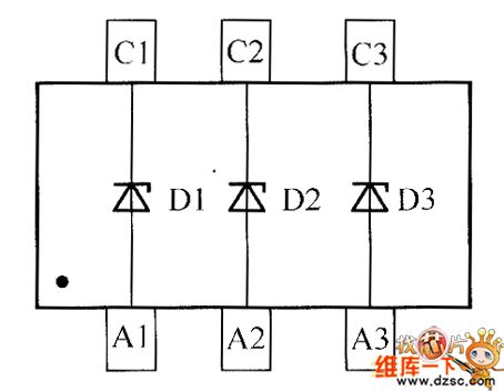
crystal diode DDZX9698TS internal circuit
Published:2011/5/31 7:47:00 Author:chopper | Keyword: crystal diode, internal
View full Circuit Diagram | Comments | Reading(343)
light-operated series switches circuit
Published:2011/5/31 7:46:00 Author:chopper | Keyword: light-operated, series switches

The light of xenon spark tube is transported to photistor MRD300 by optical fiber.The photosensitive electric current can trigger a series of thyristors after it is amplified,and offer load RL 6000V voltage.The manner of photoelectric trigger can eliminate the inductance delay generated by normal trigger's line.It requires that thyristors have the same risetime,so that can protect the circuit from triggering by those slowest inductive components.
(View)
View full Circuit Diagram | Comments | Reading(450)
level-8 touch volume controller of 74L194 circuit
Published:2011/5/11 4:56:00 Author:chopper | Keyword: touch volume controller, level-8

As shown in figure is a level-8 touch volume controller of 74L194 circuit.Multivibrator type oscillator,shifting register,touch control circuit,impedance inverter circuit form the circuit.The oscillatory frequency of multivibrator type oscillator composed of IC1(555) and R18,R19,C2 is f=1.44/(R18+2R19)C2,and the corresponding frequency of parameter in the figure is about 2Hz.The outputing square signal acts as shifting clock pulse of IC2,IC3.IC2,IC3 are bidirectional shift-registers 74LSl94,and they two concatenate to be a shift-register.IC2,IC3 will be cleared when it meets a boot-strap,and Q0~Q7 are all low level.The circuit is unchangeable and the volume is the least.The S0(pin ⑨)of IC2,IC3 is high level when we touch the sheet metal A by hands,and IC2,IC3 reach a serial rightward shift,makingLED0~LED7 illumine one by one.At the same time,with the electric current,LED8 reaches a staged growth and becomes more brilliant.The resistance of corresponding photoresistor Cds decreases,and the volume inceases gradually.The range of fluctuation is controlled by the time of touching A.When we touch metal B,IC1,IC2 will reach a serial leftward shift because the the S1(pin ⑩) is high level,makeing the volume diminish gradually. (View)
View full Circuit Diagram | Comments | Reading(1245)
electronic sound modeling mouse expeller circuit
Published:2011/6/10 7:15:00 Author:chopper | Keyword: electronic, sound modeling, mouse expeller
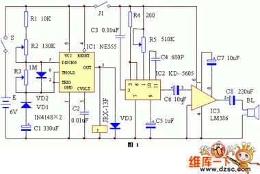
The principle of circuit is shown as picture 1.It is formed by time control circuit,meows generation circuit,power amplification circuit and so on.Time control circuit is formed by time base circuit IC1 NE555 and its peripheral resistance-capacitance component,diode.It is a impulse oscillator of adjustable dutyfactor,and its dutyfactor is controlled by R2 and R3.Meows generation circuit is formed by a CMOS integrated circuit IC2 KD-5605 and fixes meows in inner circuit by using storage technology. (View)
View full Circuit Diagram | Comments | Reading(657)
Second order active low-pass filter circuit
Published:2011/6/10 7:14:00 Author:chopper | Keyword: Second order, active low-pass filter
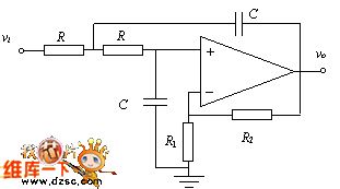


Quality factor indicates the state of bandpass filter. General requirement Q = 0.707.Then,we can get the following formula:
Cut-off frequency w0 =w =1/RC,that is:f =1/2pRC (View)
View full Circuit Diagram | Comments | Reading(1150)
Adjustable photoelectric isolation circuit
Published:2011/6/8 6:27:00 Author:chopper | Keyword: Adjustable, photoelectric isolation

This circuit modulats(modulation frequency is about 1400HZ ) the optoelectronic isolator FPA103 produced by XianTong company and demodulates the singal from detector,in order to make optoelectronic not sensitive to fluorescent lamp light but not to decrease the performance.R1,C1 regulates the voltage controlled oscillator of PLL integrated circuit within 1400HZ around,741 operational amplifier converts the triangular wave of phase-locked loop into the square wave whose duty ratio is 50%,and drives the LED of optoelectronic isolator through Q1.
(View)
View full Circuit Diagram | Comments | Reading(491)
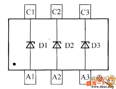
crystal diode DDZX9701TS internal circuit
Published:2011/6/1 2:07:00 Author:chopper | Keyword: crystal diode, internal
View full Circuit Diagram | Comments | Reading(345)
@ @recycle used frequency meter HP5342A HP5352A HP5350A HPE4418B
Published:2011/5/11 0:01:00 Author:Fiona | Keyword: recycle used frequency meter
High purchase/recycle used frequency meter
Liu Dan Mobile: 13546965752
Frequency meter: HP5342A, HP5343A, HP5350A / B, HP5352A, HPE4418B
Source: SMP02, SMT03, SME03, SMIQ03, FLUKE54200
Meter: HP3458A, HP3475A, HP34401A, FLUKE45
Multifunction Calibrator: FLUKE5500A, FLUKE5520A, FLUKE5720A
Contact: Liu Dan
Mobile Phone: 13546965752Tel :0769 -87,920,272Online QQ: 389556460E-mail: liaodanc@163.com
Address: No.63,Tang Xia Road,Tang Xia Town, Dongguan City
【Remarks】Long-term paying high price to site recycle used equipment:professional recycling used network analyzer,used spectrum analyzer,used oscilloscope,used sources,used comprehensive measurement and so on.The company engaged in the recovery of used equipment for years. Enjoys the reputation in the used equipment industry of Dongguan, Shenzhen, Shanghai, Tianjin, Suzhou.we provide long-term site assessing/ recycling used idle equipment, high-price recycling all kinds of used equipment in cash.Company has long-term good faith,and respects for the customer to Solute the used equipment to make your money quickly withdrawn from circulation.
Used Equipment Recycling Hot line: Mobile Phone: 13712220881 (View)
View full Circuit Diagram | Comments | Reading(729)
The voltage source circuit of 555 drive neon bulb
Published:2011/5/27 2:52:00 Author:nelly | Keyword: drive neon bulb, voltage source
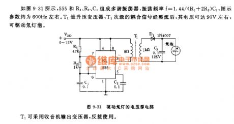
As shown in the figure 9-30,555 and R1, R2, C1 make up the astable multivibrator.The vibrational frequency: f=1.44/(R1+2R2)C1, the parameter on the figure is about 600Hz. T1 is a step-up transformer, its voltage can reach 90V and drive the neon bulb after Secondary Coupling Signal to be rectified. T1 can adopt a radio output transformer.
(View)
View full Circuit Diagram | Comments | Reading(932)
repeated timing circuit
Published:2011/5/16 2:41:00 Author:Christina | Keyword: repeated, timing
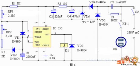
Working principle:
The repeated timing circuit is as shown in figure 1. The no steady-state circuit is composed of the IC555 RP1, R1, RP2, R2, VD1, VD2 and C1, the output port's (pin-3) high-to-low level conversion time is decided by the capacitor C1's charging-discharging time, and this is the opening and closing time of the electric appliance which is controlled by the circuit. This shows that we just need to adjust C1's charging-discharging time, so we can adjust the opening and closing time of the electric appliance which is controlled by the circuit. In this circuit, we can add the diodes VD1 and VD2 to ensure the C1's charging time and discharging time can be adjusted.
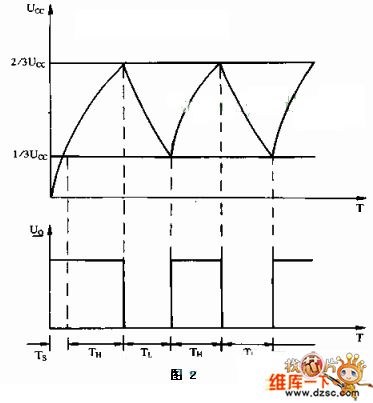
In this circuit's working process, pin-2 and pin-3's voltage changing process is as shown in figure 2. TH is the working time of the controlled electric appliance, TL is the rest time of the electric appliance.
Component selection:
In this circuit, the IC can chooses the time-base circuit such as the LM555, NE555, MA555 and 5C1555; relay K1 can choose the small and medium-size power relay with the Rated working voltage of 9V to 12V; the diode VD6 can choose the diode with 12V voltage value such as 2DW21.etc. (View)
View full Circuit Diagram | Comments | Reading(556)
555 astable multivibrator circuit
Published:2011/5/25 1:01:00 Author:Christina | Keyword: astable multivibrator

As the figure shown, if you connect 555 (or 1/2 556) with three resistance, tolerance components, it is the astable multivibrator mode. The difference between the astable multivibrator mode and the monostabillity mode is: the astable multivibrator mode's trigger port (pin-2) connects to the C of the charging & discharging circuit, but not controlled by the output trigger. (View)
View full Circuit Diagram | Comments | Reading(769)
AD620 pre-amplifier circuit
Published:2011/5/25 1:01:00 Author:Christina | Keyword: pre-amplifier

Because the string signal generator output signal's maximum value is about 1V, so the voltage drop of the sampling resistance which is connected with the network load needs to amplify the sampling signal. This circuit uses the two stages amplifier, and the preamplifier stage uses the AD620.
Figure: AD620 pre-amplifier circuit
The AD620 is designed as one kind of low power consumption amplifier, and it can be used as the small signal's pre-amplifier stage, the signal which is amplified by AD620 has small distortion. (View)
View full Circuit Diagram | Comments | Reading(4503)
Single variable dual-supply ciruit
Published:2011/6/1 21:11:00 Author:Christina | Keyword: Single variable, dual-supply

As the figure shows, the astable multivibrator is composed of the 555 and R1, C2, the oscillation frequency is about 20kHz, and the charging and discharging time constants are R1C2, so the duty ratio is 50%. The output 20kHz pulse wave is rectified and filtered by the D1, C3 and D2, C4, so the circuit outputs the ±EDD dual-power-supply. It uses the double time bases 555 to improve the load current to 50 mA. (View)
View full Circuit Diagram | Comments | Reading(1851)
Tianjin Toyota Vios circuit
Published:2011/6/1 21:12:00 Author:Christina | Keyword: Tianjin, Toyota, WeiChi

The Tianjin Toyota Vios circuit is as shown:
(View)
View full Circuit Diagram | Comments | Reading(1914)
| Pages:1757/2234 At 2017411742174317441745174617471748174917501751175217531754175517561757175817591760Under 20 |
Circuit Categories
power supply circuit
Amplifier Circuit
Basic Circuit
LED and Light Circuit
Sensor Circuit
Signal Processing
Electrical Equipment Circuit
Control Circuit
Remote Control Circuit
A/D-D/A Converter Circuit
Audio Circuit
Measuring and Test Circuit
Communication Circuit
Computer-Related Circuit
555 Circuit
Automotive Circuit
Repairing Circuit


