
Circuit Diagram
Index 1759
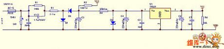
The 90W, 15V, 6A switching voltage stabilization power supply circuit
Published:2011/5/19 18:31:00 Author:Christina | Keyword: switching, voltage stabilization, power supply
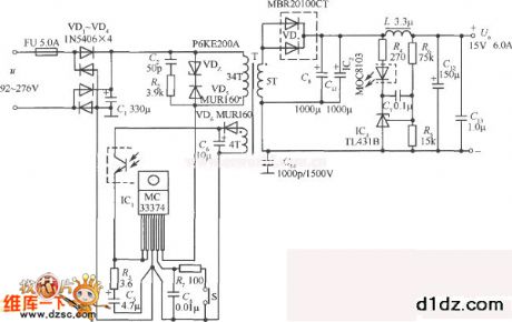
The 90W, 15V, 6A switching voltage stabilization power supply circuit which is composed of the MC33374 is as shown. This circuit uses the E28 type ferrite core, the primary coil and the feedback coil's wire diameter will not change, the turn numberis 34 turns and 4 turns, respectively. The secondary coil uses the φ0.8mm enameled double thread paratactic around wire. The core's air-gap is 0.56mm. The specifications of the power supply areas shown in the table:
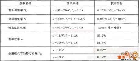
The specifications of the power supply areas shown in the table:
(View)
View full Circuit Diagram | Comments | Reading(996)
Digital tube dynamic scanning circuit
Published:2011/5/25 21:40:00 Author:Christina | Keyword: Digital tube, dynamic scanning
One group of digital tube dynamic scanning display needs two groups of control signal: one group is the font code which is output by the field output port, this font code can be used to control the displaying font, called the segment-code, another group is the control signal which is output by the bit output port, this control signal can be used to select which bit of the digital tube will be working, called the bit-code.
The digital tube is composed of seven bar-type LEDs and a circular LED, so there are 8 section lines that can be used in the 8-bit parallel system. There are two kinds of digital tubes: the altogether cathode and the altogether anode. The public cathode of the altogether anode digital tube connects to the ground.
(View)
View full Circuit Diagram | Comments | Reading(502)
Use the LM386 as the sine wave oscillator circuit
Published:2011/5/25 21:44:00 Author:Christina | Keyword: sine wave, oscillator circuit
The driver alcohol detection alarm controller circuit is as shown in the figure. The QM-NJ9 is alcohol gas sensor, if it detects the alcohol odor, the resistance of QM-NJ9 between A and B will shrink, and the wiper potential of potentiometer RPl will rise up. When the voltage level is 1.6V, the ICl high-power switching device TWH8778 is connected to make the IC2 voice IC TM801 to work, the output is amplified by the IC3 integrated amplifier LM386, and then the amplified output drives the speaker BLl to send out alarm. (View)
View full Circuit Diagram | Comments | Reading(962)
Pressurization transform power supply circuit with the frequency automatic offset features composed of the MAX630
Published:2011/5/25 19:20:00 Author:Christina | Keyword: Pressurization, transform, power supply, frequency, automatic offset

The low voltage frequency offset pressurization transform power supply which is composed of the MAX630's low battery voltage detection function is as shown. The feature of this circuit is: when the battery voltage is lower than nominal value (3V), about 2V, this circuit can highly efficiency (85%) supply the 40mA,5V DC voltage at the output port. The process is: the battery voltage drops, and causes the voltage of MAX630's pin1 (from the R3 and R4's separate pressure of the battery electric) todrop too, when the voltage is lower than the battery voltage detection comparator's threshold voltage (1.31V), the detection output port (pin-8) LBD becomes the low-level voltage, this connects the C1 together with the Cx and reduces MAX630 internal oscillator's frequency.
(View)
View full Circuit Diagram | Comments | Reading(504)
stable threshold voltage circuit
Published:2011/5/25 19:18:00 Author:Christina | Keyword: stable, threshold, voltage circuit
Figure: stable threshold voltage circuit (View)
View full Circuit Diagram | Comments | Reading(792)
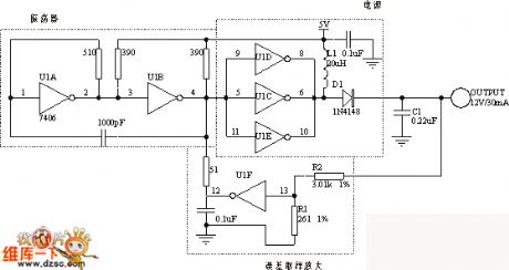
CD4093 sine wave switching to square wave circuit
Published:2011/6/9 21:19:00 Author:John | Keyword: sine wave, square wave

The input sine wave voltage supplies power to IC1 through the half-wave double voltage circuit, which is composed of C1, C2 and D1, D2. IC1A constitutes amplifier in order to amplify the input signal. The signal would be transformed into a square wave signal through the IC1B and IC1C. Then square wave signalis output after the amplification by IC1D, IC1E and IC1F. R2 is used to adjust the output signal amplitude. The circuit as shown can output square wave with good performance within the 20Hz-20KHz. During the application, the valid value for the input sine wave is suggested to be greater than 1.5 volts in order to ensure the quality of the output signal. Minimum input voltage sine wave must be greater than 750mV and the peak value for output signal is about 2 volts at this time.
Figure 1 sine wave switching to square wave circuit (View)
View full Circuit Diagram | Comments | Reading(3885)
LED display driven by 74HC164 circuit (common cathode)
Published:2011/6/7 10:13:00 Author:John | Keyword: LED
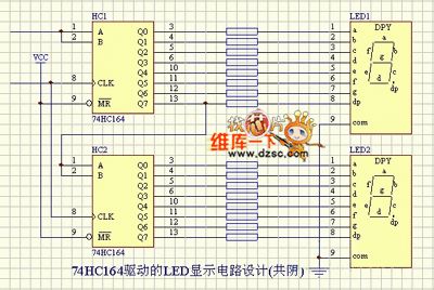
LED display 74HC164 driver circuit is shown in the following.
(View)
View full Circuit Diagram | Comments | Reading(2644)
Logic level by NE555 and MOSFET interface circuit
Published:2011/6/9 21:20:00 Author:John | Keyword: Logic level, MOSFET interface

In the circuit, NE555 is the non-steady-state multivibrator with oscillation frequency of 70KHz. Control input signals by reset pin (pin 4) on / off controls its state of oscillation. When pin 4 inputs high electricity, the oscillator starts to work. When pin 4 inputs high electricity, the oscillation stops. Output of NE555’s pin 3 provides input voltage for dual-voltage rectifier circuit composed of VD1, VD2, C3 and C4. And the output of dual-voltage rectifier circuit is 8•5V. Digital logic control signal is added to NE555’s reset pin (pin 4) through the optical coupler 4N35. The optical coupler would do electrical isolation between the digital logic control signal and the high load.
(View)
View full Circuit Diagram | Comments | Reading(2046)
LED driven by eight 74HC595 circuit
Published:2011/6/8 9:37:00 Author:John | Keyword: LED
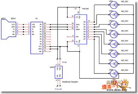
LED driven by eight 74HC595 circuits areshown in the following.
(View)
View full Circuit Diagram | Comments | Reading(6348)
RC Step-down circuit
Published:2011/5/18 19:16:00 Author:John
RC Step-down circuit is shown below.
(View)
View full Circuit Diagram | Comments | Reading(770)
Oscillator phase-shifting circuit
Published:2011/5/19 0:43:00 Author:John | Keyword: Oscillator phase-shifting

Oscillator phase-shifting circuit is shown below.
(View)
View full Circuit Diagram | Comments | Reading(431)
FET oscillator circuit
Published:2011/5/19 0:43:00 Author:John | Keyword: FET oscillator

FET oscillator circuit is shown below.
(View)
View full Circuit Diagram | Comments | Reading(997)
Produced by six-inverter DC / DC conversion circuit
Published:2011/5/27 7:07:00 Author:John | Keyword: six-inverter
The circuit adjusts the voltage by controlling TTL switching threshold. U1A and U1B form the oscillator andtheoscillator'sswitching frequency is less than 1MHz. Output of oscillator drives three parallel inverters U1C, U1D and U1E. They can provide higher output current and output power. The internal output transistor, L1 and D1 form a standard boost converter. When the output is low, the current only flows through the inductor L1. When the output is higher, the energy stored in the inductor forces the anode of D1 to become higher. C1 conducts to charge D1.
(View)
View full Circuit Diagram | Comments | Reading(853)
battery car charger production with low cost and high reliability circuit
Published:2011/5/27 7:08:00 Author:John | Keyword: battery car charger
Currently, MC3842 is the most widely used and the earliest single-ended drive for directly driving switch MOS FET. MC3842 can not put a stable voltage. At the same time, it also has a load current control. Thus, MC3842 is often referred as current control type switch power supply drive. There is no doubt that the charger has the unique advantage, resulting from features of MC3842. Only very few external components are needed to achieve constant pressure output. And the charge current can be controlled at the same time. Especially, that MC3842 can directly drive MOS FETsubstantially increase the reliability of the charger.
(View)
View full Circuit Diagram | Comments | Reading(887)
Dong Fang rice cooker and porridge device circuit
Published:2011/5/27 7:08:00 Author:John | Keyword: rice cooker, porridge device

Rice cooker and porridge device circuit is shown below.
(View)
View full Circuit Diagram | Comments | Reading(674)
AC photoelectric switch circuit
Published:2011/5/27 7:09:00 Author:John | Keyword: photoelectric switch

The circuit acts when the light intensity is over 700LX. . At this moment, the phototransistor BFY52 and transistor BPX25 trigger current to thyristor BTY91/800R. Where there is bright light on the phototransistor, the trigger pulse always occurs at each positive half cycle beginning of about 6 °. The maximum arithmetic average of load-through DC half-wave current is 16A.
Regulator BZY88/C5, transistor T1 and its connection resistor 390Ω form to limit the voltage in trigger circuit to not exceed 6V. Diode BYX45/800R is used to block the negative half-cycle grid voltage. The resistor 33Ω and capacitor 0.1μF are used to protect the thyristor against over-voltage.
(View)
View full Circuit Diagram | Comments | Reading(848)
RC sine wave oscillator circuit
Published:2011/6/9 21:17:00 Author:John | Keyword: sine wave oscillator


Common RC sine wave oscillator circuit is RC series-parallel sine wave oscillator circuit. It is also called Wien bridge sine wave oscillator circuit.
Series-parallel network here is regarded as an option for frequency and feedback network. The circuit is just shown in Figure (1):
Its starting condition is and its oscillation frequency is .It is mainly used for low-frequency oscillations. To generate a higher frequency sinusoidal signal, the LC sine wave oscillator circuit is generally adopted. Its oscillation frequency is . Quartz oscillator is characterized by its particularly stable oscillation frequency, so it is commonly used in occasions with highly stable oscillation frequency.
(View)
View full Circuit Diagram | Comments | Reading(596)
instrumentation amplifier with ±100 volt common mode range circuit
Published:2011/6/9 21:18:00 Author:John | Keyword: instrumentation amplifier

Instrumentation amplifier with ±100 volt common mode range circuit is shown below.
(View)
View full Circuit Diagram | Comments | Reading(799)
Optical shaft encoder photodiode circuit
Published:2011/6/9 21:18:00 Author:John | Keyword: Optical shaft encoder, photodiode
Light emitted from incandescent light bulb reaches the photodiode through the lens, cylindrical lens and the slot of chrome optical encoding disk. Coding plate engraves according to cyclic binary code. If it is corresponded to n-bit binary code, n photodiodes should be ranked in the optical narrow line behind the slot. 16-bit requires the width of optical slit of 20μm, so the good reliability can be ensured. Microampere meter reads about 0.1μA when there exists light. And it reads about 6~10μA when there is no light. 3DG5DX2 is the composite pipe, which has a rather greater magnification and emitter output. Two pieces of 3DK2 composite Schmitt trigger, whose function is to coin. When there exists light, the output is less than 0.5V. When there is no light, the output reaches +6V.
(View)
View full Circuit Diagram | Comments | Reading(1041)
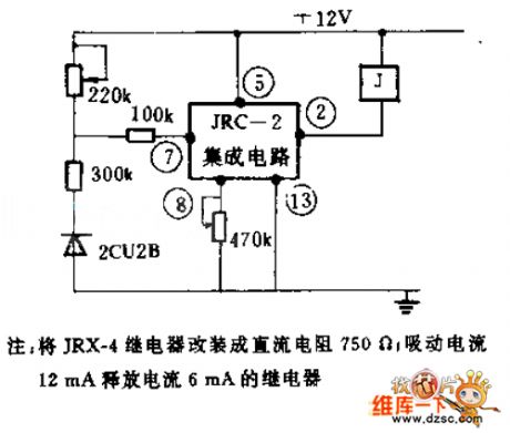
Automatic wire counting machine circuit
Published:2011/6/8 9:37:00 Author:John | Keyword: Automatic wire counting machine
Photodiode 2CU22R accepts the optical signal uploaded to the machine. Such signals control sensitive relay to act through being amplified by the transistor. Then the alarm clock is driven to indicate the number of wires with the pointer.
(View)
View full Circuit Diagram | Comments | Reading(966)
| Pages:1759/2234 At 2017411742174317441745174617471748174917501751175217531754175517561757175817591760Under 20 |
Circuit Categories
power supply circuit
Amplifier Circuit
Basic Circuit
LED and Light Circuit
Sensor Circuit
Signal Processing
Electrical Equipment Circuit
Control Circuit
Remote Control Circuit
A/D-D/A Converter Circuit
Audio Circuit
Measuring and Test Circuit
Communication Circuit
Computer-Related Circuit
555 Circuit
Automotive Circuit
Repairing Circuit