
Circuit Diagram
Index 1747
Intermittent power controller circuit diagram 5
Published:2011/6/16 4:01:00 Author:Lucas | Keyword: Intermittent , power controller

The intermittent power control circuit is composed of the power supply circuit and timing control circuit, and the circuit is shown as the Figure. Power supply circuit is composed of the power switch s, power transformer T, bridge rectifier UR, filter capacitor C3 and Zener VS . Timing control circuit consists of the time-base integrated circuit IC, transistor V, Relay K, potentiometers RP1, RP2, capacitor C1, C2, resistor R and diode VD. R uses the 1/4W carbon film resistor. BP1 and RP2 use organic, solid potentiometers. C1 and C3 select the aluminum electrolytic capacitors with the voltage in 25V.
(View)
View full Circuit Diagram | Comments | Reading(465)
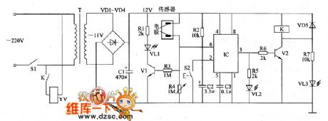
Agricultural automatic water valve circuit diagram 2
Published:2011/6/16 3:57:00 Author:Lucas | Keyword: Agricultural , automatic , water valve
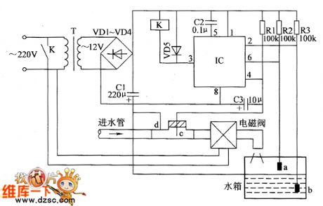
The agricultural automatic water valve circuit is composed of the power supply circuit, detection circuit and control circuit, and the circuit is shown as the Figure 1. Power supply circuit is composed of the power transformer T, rectifier diodes VD1 ~ VD4 and filter capacitor C1 and so on. Detection circuit is composed of the high water level detection electrode a, low water level detection electrode b and water inlet pipe detection electrode c and so on. Control circuit consists of the time-base integrated circuit IC, relay Κ and the external components. R1 ~ R3 use 1/4W or 1/8W metal film resistors. VD1 ~ VD5 use 1N4001 or 1N4007 silicon rectifier diodes.
(View)
View full Circuit Diagram | Comments | Reading(633)
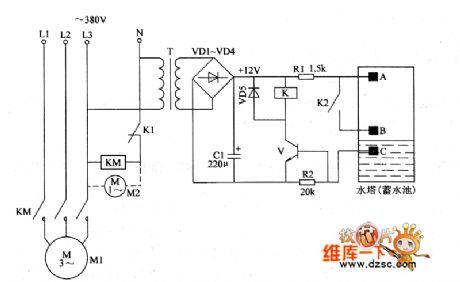
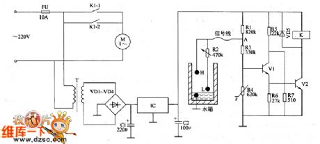
Agricultural irrigation controller circuit diagram 1
Published:2011/6/16 4:11:00 Author:Lucas | Keyword: Agricultural, irrigation controller

The agricultural irrigation controller circuit is composed of the power supply circuit and the water level detection control circuit, and the circuit is shown as the Figure. Power supply circuit is composed of the fuse FU, power transformer T, bridge rectifier UR, filter capacitors C1, C2, current limiting resistor R3 and two terminal integrated voltage regulator IC. Water level detection control circuits is composed of the high water level electrode A, low water level electrode B, main electrode C, resistors RI, R2, transistor V, Relay K, diode VD, AC contactor KM and other components. R1 and R2 use 1/4W carbon film resistors or metal film resistors.
(View)
View full Circuit Diagram | Comments | Reading(983)
Agricultural automatical water feeder circuit diagarm 18
Published:2011/6/14 5:58:00 Author:Lucas | Keyword: Agricultural , automatical water feeder
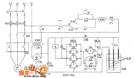
The agricultural automatical water feeder circuit is composed of the power supply circuit, water level detection control indicating circuit, starter control circuit, and the circuit is shown as the chart 1. Power supply circuit is composed of the power transformer T, bridge rectifier and filter capacitor C. The water level detection control indicating circuit consists of water level detection electrodes a ~ c, six NOT gate IC IC (D1 ~ D6), resistors R1, R2, relay K, color light-emitting diode VL and diode VD. The starter control circuit is composed of the knife switch Q, fuses FU1 ~ FU3, power switch S1, manual / automatic control switch S2, stop button S3, start button S4, AC contactor KM and thermal relay ER.
(View)
View full Circuit Diagram | Comments | Reading(437)
Agricultural automatical water feeder circuit diagarm 17
Published:2011/6/16 5:28:00 Author:Lucas | Keyword: Agricultural , automatical , water feeder

The agricultural automatical water feeder circuit is composed of the power supply circuit, bistable circuit and water level measurement and control circuit, and the circuit is shown as the Figure 1. Power supply circuit is composed of the power transformer T, bridge rectifier UR, filter capacitors C1, C2, and three-terminal voltage regulator integrated circuit IC. Bistable circuit consists of transistors V2, V3 and the external components. Water level measurement and control circuit consists of transistors V1, V4, Reed A, Reed B, and resistors R1, R2, R6 ~ R8, R14 and so on. R1 ~ R14 use 1/4W carbon film resistors or metal film resistors. VD1 and VD2 use 1N4148 silicon switch diodes.
(View)
View full Circuit Diagram | Comments | Reading(402)
Automatic sprinkler controller circuit diagram 5
Published:2011/6/16 5:24:00 Author:Lucas | Keyword: Automatic , sprinkler controller

The automatic sprinkler controller circuit is composed of the power supply circuit and humidity measurement and control circuit, and the circuit is shown as the Figure. Power supply circuit is composed of the power transformer T, rectifier diodes VD1 ~ VD4, filter capacitors C1 ~ C3 and three-terminal integrated regulators ICl, IC2 and so on. Humidity measurement and control circuits is composed of the humidity detector, NOT gate integrated circuit IC3 (Dl, D2), transistor V, Relay K and the external components. R1 uses l/2W carbon film resistor: R2 ~ R5 select l/4W carbon film resistors. RP1 ~ RP3 use small synthetic carbon film potentiator.
(View)
View full Circuit Diagram | Comments | Reading(1460)
Agricultural automatical water feeder circuit diagarm 16
Published:2011/6/14 5:53:00 Author:Lucas | Keyword: Agricultural , automatical water feeder
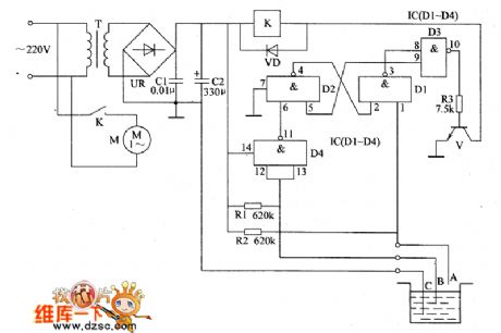
The agricultural automatical water feeder circuit is composed of the power supply circuit and water level detection control circuit, and the circuit is shown as the chart 1. Power supply circuit is composed of the power transformer T, bridge rectifier UR and filter capacitors C1, C2. Water level detection control circuit is composed of the water level detection electrodes A ~ C, four NAND gates integrated circuit IC (D1 ~ D4), transistor V, resistors R1 ~ R3, relay K and diode VD. AC 220V voltage is bucked by T , rectified by UR and filtered by C1, C2 to provide 12V voltage for relay K and IC. R1 ~ R3 use the carbon film 1/4W resistors or metal film resistors.
(View)
View full Circuit Diagram | Comments | Reading(417)
Automatic sprinkler controller circuit diagram 4
Published:2011/6/16 5:13:00 Author:Lucas | Keyword: Automatic , sprinkler controller

The automatic sprinkler controller circuit is composed of the power supply circuit and timing control circuit, and the circuit is shown as the Figure. Power supply circuit is composed of the fuse FU, power switch S1, step-down capacitor C1, resistor RI, rectifier diodes VD1, VD2, filter capacitor C3, power indicator LED VL1 and Zener vs. The timing control circuit is composed of the time-base integrated circuit IC, timing capacitor C5, Triac VT, relay K, manual / automatic switch S2 and the related external components. R1 ~ R6 select I/4W carbon film resistors or metal film resistors.
(View)
View full Circuit Diagram | Comments | Reading(2009)
Agricultural automatical water feeder circuit diagarm 15
Published:2011/6/14 5:49:00 Author:Lucas | Keyword: Agricultural, automatical water feeder

The agricultural automatical water feeder circuit is composed of the water level detection control circuit, sound and light alarm circuit and power supply circuit,and the circuit is shown as the chart 1. Power supply circuit is composed of the power switch s, power transformer T, rectifier diodes VD1 ~ VD4, fuse FU, filter capacitor C and the three-terminal voltage regulator integrated circuit IC. Water level detection control circuit consists of water level detection electrodes A ~ H, transistors V1 ~ V6, relays K1 ~ K3, diodes VD5 ~ VD7 and resistors R1 ~ R3. Sound and light alarm circuit is composed of the lights HL1, HL2, HA, and alarm control contacts K1 ~ K3. R1 ~ R3 select 1/4W carbon film resistors or metal film resistors.
(View)
View full Circuit Diagram | Comments | Reading(458)
Automatic sprinkler controller circuit diagram 3
Published:2011/6/16 5:08:00 Author:Lucas | Keyword: Automatic , sprinkler controller

The automatic sprinkler controller circuit is composed of the +12 V power supply circuit, light control circuit and irrigation control circuit, and the circuit is shown as the Figure. +12 V power supply circuit is composed of the knife switch Q, fuse FU2, power switch S1, power transformer T, rectifier diodes VD1 ~ VD4, filter capacitors C1, C2, and three-terminal voltage regulator integrated circuit IC1. Light control circuit is composed of the phototransistor VI, potentiometer RP, resistors R3 ~ R6, capacitors C5, C6, time-base integrated circuit IC3, transistor V2.RI ~ R8 select 1/4W metal film resistors or carbon film resistors.
(View)
View full Circuit Diagram | Comments | Reading(3134)
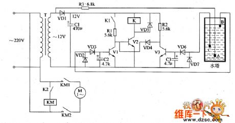
Agricultural automatical water feeder circuit diagarm 14
Published:2011/6/14 6:09:00 Author:Lucas | Keyword: Agricultural , automatical water feeder
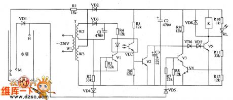
The agricultural automatical water feeder circuit is composed of the power supply circuit, water level detection circuit, control circuit and control implementation circuit, and the circuit is shown as the chart 1. Power supply circuit is composed of the power transformer T, rectifier diodes VD2, VD3, and filter capacitors C1, C2. Water level detection circuit is composed of water level detecting electrode H, electrode L, electrode M, diode VD1 and resistor R1. Control circuit consists of transistors V1 ~ V4, resistosr R2 ~ R9, R11, R12, diodes VD4, VD5, optical coupler VLC and capacitor C3. Control implementation circuit consists of the transistor V5, diodes VD6 ~ VD8 and relay K.
(View)
View full Circuit Diagram | Comments | Reading(433)
Agricultural automatical water feeder circuit diagarm 13
Published:2011/6/14 5:45:00 Author:Lucas | Keyword: Agricultural , automatical water feeder
The agricultural automatical water feeder circuit is composed of the electrode A, electrode B, time-base integrated circuit IC, control transistor V, power transformer T, rectifier diodes VD1 ~ VD4 and relay K and other components, and the circuit is shown as the chart 1. AC 220V voltage is bucked by T, rectified by VD1 ~ VD4 and filtered by capacitor C1 to provide DC 12V voltage (Vcc) for IC as the operating voltage. R1 ~ R4 select l/4W or 1/8W carbon film resistors. Cl chooses the aluminum electrolytic capacitor with the voltage in 16V; C2 and C3 select monolithic capacitors. VD1 ~ VD5 use 1N4007 type silicon rectifier diodes. V uses C8050 silicon PNP transistor. K selects JRX-13F 12V DC relay.
(View)
View full Circuit Diagram | Comments | Reading(430)
Agricultural automatical water feeder circuit diagarm 12
Published:2011/6/14 5:41:00 Author:Lucas | Keyword: Agricultural, automatical , water feeder

The agricultural automatical water feeder circuit is composed of the power supply circuit, water level detection circuit and control implementation circuit,and the circuit is shown as the chart 1. Power supply circuit is composed of the power transformer T, rectifier diodes VD1 ~ VD4 and filter capacitor C1. Water level detection circuit is composed of the high water level electrode A, low water level electrode B and the main electrode C. Control implementation circuit is composed of the IC and relay K, AC contactor KM and other components. AC 220V voltage is bucked by T, rectified by VD1 ~ VD4 and filtered by C1 to provide 10V DC voltage for IC. RI and R2 select 1/4W carbon film resistors. C1 chooses the aluminum electrolytic capacitor with the voltage in 16V; C2 uses the polyester capacitor or monolithic capacitor.
(View)
View full Circuit Diagram | Comments | Reading(831)
Automatic sprinkler controller circuit diagram 1
Published:2011/6/16 4:59:00 Author:Lucas | Keyword: Automatic , sprinkler controller

The automatic sprinkler controller circuit is composed of the clock timing controller, monostable flip-flop, bistable flip flop, electronic switch, self-excited multivibrator, counter, solenoid valve control circuit and power supply circuit, and the circuit is shown as the Figure. Power supply circuit is composed of the fuse FU, power switch SO, power transformer T, bridge rectifier UR and filter capacitors C11, C12. Self-excited multivibrator is composed of the time-base IC ICS and the external components, and it is used to generate the count pulse. R1 ~ R26 choose l/4W or 1/8W carbon film resistors.
(View)
View full Circuit Diagram | Comments | Reading(3019)
Agricultural automatical water feeder circuit diagarm 11
Published:2011/6/14 6:25:00 Author:Lucas | Keyword: Agricultural , automatical water feeder
The agricultural automatical water feeder circuit is composed of the power supply circuit, water level detection circuit and control implementation circuit, and the circuit is shown as the chart 1. Power supply circuit is composed of the power transformer T, rectifier diodes VD1 ~ VD4 and filter capacitor C. Water level detection circuit is composed of the high water level electrode A, low water level electrode B and the main electrode C. Control implementation circuit is composed of the relay K, control transistor V and AC contactor KM and other components. AC 220Y voltage is bucked by T, rectified by VD1 ~ VD4 and filtered by C to produce the DC 12V voltage for control implementation circuit.
(View)
View full Circuit Diagram | Comments | Reading(430)
Agricultural automatical water feeder circuit diagarm 10
Published:2011/6/14 6:21:00 Author:Lucas | Keyword: Agricultural , automatical water feeder
The agricultural automatical water feeder circuit is composed of power supply circuit, water level detection circuit and pump control circuit, and the circuit is shown as the chart 1. The power supply circuit is composed of the power transformer T, rectifier diode VD1 and filter capacitor C1 and other components. Water level detection circuit is composed of the main electrode A, high water level electrode B, low water level electrode C and control tubes V1, V3 and so on. Pump control circuit consists of the relay K, relay drive tube V2, AC contactor KM and so on. R1 ~ R3 select 1/4W carbon film resistors. C1 ~ C3 select the aluminum electrolytic capacitors with the voltage in 16V. VD1 ~ VD7 use 1 N4007 silicon rectifier diodes.
(View)
View full Circuit Diagram | Comments | Reading(959)
Agricultural automatical water feeder circuit diagarm 19
Published:2011/6/14 6:15:00 Author:Lucas | Keyword: Agricultural, automatical water feeder
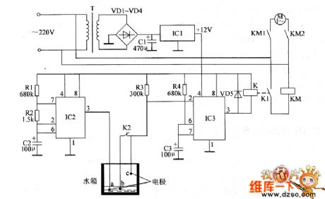
The agricultural automatical water feeder circuit is composed of the power supply circuit, multivibrator, monostable trigger, relay K, AC contactor KM and water detection electrodes (a ~ c) and other components, and the circuit is shown as the chart 1. Power supply circuit is composed of the power transformer T, rectifier diodes VD1 ~ VD4, three-terminal integrated voltage regulator IC1 and filter capacitor C1. Multivibrator is composed of the time-base integrated circuit IC2, resistors R1, R2 and capacitor C2 and so on. The monostable trigger is composed of the time-base integrated circuit IC3, resistors R3, R4, and capacitor C3 and other components. R1 ~ R4 select 1/4W carbon film resistors.
(View)
View full Circuit Diagram | Comments | Reading(436)
Agricultural automatical water feeder circuit diagarm 8
Published:2011/6/14 6:04:00 Author:Lucas | Keyword: Agricultural , automatical water feeder
The agricultural automatical water feeder circuit is composed of the power supply circuit, detection circuit, monostable trigger circuit, control circuit and the water full alarm circuit and other components, and the circuit is shown as the chart 1. Power supply circuit is composed of the power switch S1, power transformer T, rectifier diodes VD1 ~ VD4 and filter capacitor C1. Water level detection circuit is composed of the water level detecting sensor (electrode) and variable resistor Ⅲ and so on. Monostable trigger circuit consists of time-base integrated circuit IC and external related components. Control circuit is composed of the relay K, driver transistor V2 and other components.
(View)
View full Circuit Diagram | Comments | Reading(418)
Agricultural automatical water feeder circuit diagarm 7
Published:2011/6/16 6:02:00 Author:Lucas | Keyword: Agricultural , automatical, water feeder
The agricultural automatical water feeder circuit is composed of the power supply circuit, water level detection circuit and control circuit, and the circuit is shown as the Figure 1. Power supply circuit is composed of the power transformer T, rectifier diodes VD1 ~ VD4, filter capacitors C1, C2 and integrated three-terminal regulator IC. Detection circuit consists of the upper electrode H, lower electrode L, variable resistor R2 and transistors V1 and so on. Control circuit consists of transistor V2, relay K1 and other components. R1, R3 and R5 ~ R7 select 1/4W carbon film resistors; R2 uses small full-sealed variable resistor.
(View)
View full Circuit Diagram | Comments | Reading(559)
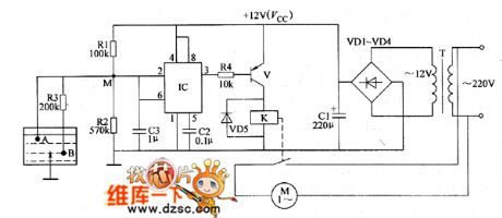
Agricultural automatical water feeder circuit diagarm 6
Published:2011/6/16 5:58:00 Author:Lucas | Keyword: Agricultural, automatical, water feeder

The agricultural automatical water feeder circuit is composed of the power supply circuit, water level detection circuit , control implementation circuit, and the circuit is shown as the Figure 1. Power supply circuit is composed of the knife switch Q, fuse FU, power transformer T, rectifier diodes VD1 ~ VD4, filter capacitor C1, resistor R1 and limiting regulator diode VS. Water level detection circuit consists of the high water level electrode H, low water level electrode L and the main electrode M. Control implementation circuit is composed of the transistor V, Relay K, time-base integrated circuit IC, diodes VD5 ~ VD8 and external RC components.
(View)
View full Circuit Diagram | Comments | Reading(538)
| Pages:1747/2234 At 2017411742174317441745174617471748174917501751175217531754175517561757175817591760Under 20 |
Circuit Categories
power supply circuit
Amplifier Circuit
Basic Circuit
LED and Light Circuit
Sensor Circuit
Signal Processing
Electrical Equipment Circuit
Control Circuit
Remote Control Circuit
A/D-D/A Converter Circuit
Audio Circuit
Measuring and Test Circuit
Communication Circuit
Computer-Related Circuit
555 Circuit
Automotive Circuit
Repairing Circuit