
Circuit Diagram
Index 1744
HT6308 Integrated Circuit Typical Application Circuit
Published:2011/6/15 0:34:00 Author:Robert | Keyword: Integrated Circuit, Typical, Application

The Ht6308 is a fan single-chip micro-computer IC which widely used in many kinds of fan program control circuits.
The fan control system typical application circuit composed of HT6308 IC is shown in the picture.
The picture shows the HT6308 IC's typical application circuit. (View)
View full Circuit Diagram | Comments | Reading(571)
Integrated Voltage Comparator Circuit
Published:2011/6/14 23:17:00 Author:Robert | Keyword: Integrated, Voltage, Comparator

The integrated voltage comparator is a special operational amplifier. The operational amplifier is working in open-loop mode. Because its open-loop gain is bery big, the comparator's output is offen high voltage level or low voltage level.
The integrated voltage comparator is a common signal processing unit circuit which is widely used in compare of signal amplitude and choice of signal amplitude and waveform transformation and shaping and so on.
Some common integrated voltage comparator's pinout is shown in the picture.
(a)Single Comparator LM311/CJ0311. (b)Double Comparator LM393. (c)High-Speed Comparator AD790. (d)Quatuor Comparator LM339/CJ-399.
(View)
View full Circuit Diagram | Comments | Reading(643)
HM9110E Integrated Circuit Typical Application Circuit
Published:2011/6/14 23:18:00 Author:Robert | Keyword: Integrated Circuit, Typical, Application

The HM9110E is a communication single-chip micro-computer integrated circuit produced by the Hitachi company which is widely used for dial-up and control circuit in communications equipments.
The dial and control typical application circuit composed of HM9110E integrated circuit is shown in the picture.
The picture shows the HM9110E integrated circuit's typical application circuit. (View)
View full Circuit Diagram | Comments | Reading(643)
HIC1026A Integrated Circuit Typical Application Circuit
Published:2011/6/14 23:19:00 Author:Robert | Keyword: Integrated Circuit, Typical, Application

The HICl026A is a multi-function power integrated circuit produced by the Hitachi company which is widely used in Toshiba AG series rear-projection color TV.The protection module typical application circuit composed of HIC1026A integrated circuit is shown in the picture (this picture is TV original picture and it has not fixed the graphic symbols which are not meeting the standard).
The picture shows the HICl026A integrated circuit's typical application circuit. (View)
View full Circuit Diagram | Comments | Reading(782)
HIC1026A Integrated Circuit Internal Principle Circuit
Published:2011/6/14 23:20:00 Author:Robert | Keyword: Integrated Circuit, Internal, Principle

The HICl026A is a multi-function power integrated circuit produced by the Hitachi company which is widely used in Toshiba AG series rear-projection color TV.
The picture shows the HICl026A integrated circuit's internal principle circuit.
(View)
View full Circuit Diagram | Comments | Reading(587)
HA31002P Integrated Circuit Typical Application Circuit
Published:2011/6/14 23:20:00 Author:Robert | Keyword: Integrated Circuit, Typical, Application

The HA31002P is aelectronic bell integrated circuit produced by Hitachi company which is widely used in communication equipments such as cordless phones andcorded phones and so on.
The picture shows the HA31002P integrated circuit's typical application circuit. (View)
View full Circuit Diagram | Comments | Reading(1824)
Keyboard input circuit
Published:2011/6/17 11:38:00 Author:John | Keyword: Keyboard

Keyboard circuit is mainly used to input data in order to achieve human-computer interaction. The design of system's keyboard is the realization of matrix keyboard through scanning. Keyboard circuit is as shown in the figure.
It can be seen from the figure that this matrix keyboard is composed of lines and columns. P1.0 and P1.1 compose columns of the keyboard and P1.2, P1.3, P1.4, P1.5 and P1.6 compose lines of the keyboard. Lines of the keyboard is regarded as a keyboard’s controling output end and columns of the keyboard is regarded as a keyboard’s controling input end.
(View)
View full Circuit Diagram | Comments | Reading(1417)
Mazda 94THUNDERBIRD (with DRL) headlamp and fog lamp circuit
Published:2011/6/17 11:05:00 Author:John | Keyword: headlamp, fog lamp
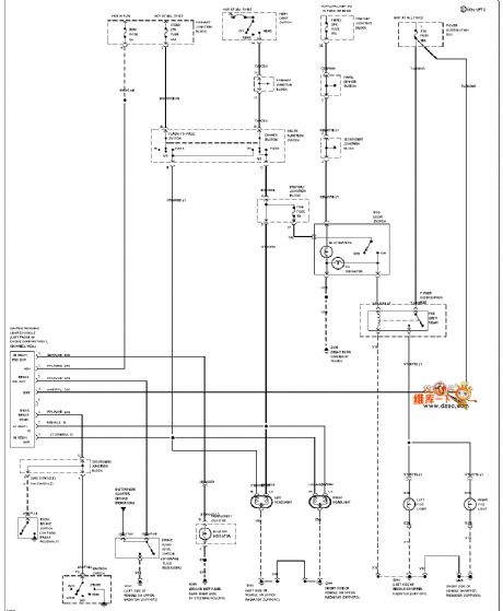
Mazda 94THUNDERBIRD (with DRL) headlamp and fog lamp circuit is shown below.
(View)
View full Circuit Diagram | Comments | Reading(559)
QS6M4 internal circuit
Published:2011/6/13 19:39:00 Author:John

QS6M4 internal circuit is shown below.
(View)
View full Circuit Diagram | Comments | Reading(475)
Crystal Portsmout oscillator circuit
Published:2011/6/20 0:19:00 Author:John | Keyword: oscillator
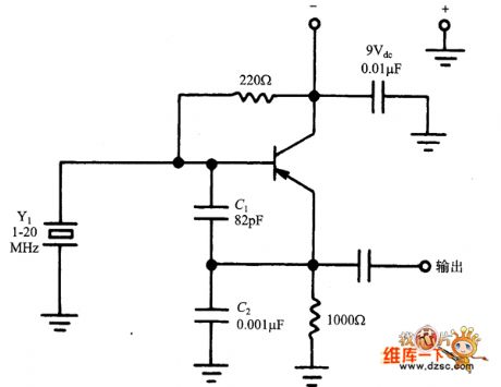
Crystal Portsmout oscillator circuit is shown below.
(View)
View full Circuit Diagram | Comments | Reading(661)
Cole Rapids oscillator circuit
Published:2011/6/20 0:20:00 Author:John | Keyword: oscillator
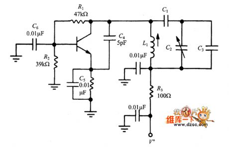
Cole Rapids oscillator circuit is shown below.
(View)
View full Circuit Diagram | Comments | Reading(620)
The digital frequency doubler of square wave output formed by MIC74121
Published:2011/6/17 9:28:00 Author:Borg | Keyword: digital frequency doubler, square wave
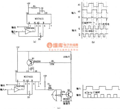
In the figure is the digital frequency doubler of square wave output. Usually, a digital frequency doubler works by the 2 output narrow pulses which are generated by the front-end and rear-end of the input pulse. In figure (a) is a basic frequency doubler circuit, A1, A2 and B are the triggering front-end of the single stable multi-resonance oscillator (MIC74121). Only when either of A1 and A2 is 1 , the other is 0 and B is 1 is the circuit triggered. After the rising edge of the input signal goes along td (the transiting time delay of the phase inverter), the single steady multi-resonance oscillator is triggered. (View)
View full Circuit Diagram | Comments | Reading(2578)
The 3~6v adjustable power supply composed of 5G14
Published:2011/6/15 2:13:00 Author:Borg | Keyword: adjustable power supply

View full Circuit Diagram | Comments | Reading(563)
The low-voltage, high-efficiency and stable-voltage adjustable power supply
Published:2011/6/15 23:33:00 Author:Borg | Keyword: low-voltage, high-efficiency, stable-voltage

The weakness of the ordinary serial stable power supply is that the drive working voltage of the adjuster is higher that the output voltage, which leads to the large pole voltage difference of c and e, so part of the power is consumed and the efficiency is reduced. For example, if the output current of the 12V stable power supply of a black-white TV set is about 1A, the voltage drop of the adjusting pipe is 7.5V, the power consumption of the adjuster is 7.5W. It is not only low-efficient, but also becomes a heat source which needs a large-size heat emitter to cool the adjusting pipe.
(View)
View full Circuit Diagram | Comments | Reading(560)
The adjustable stable power supply with functions of overload and short circuit protection
Published:2011/6/15 23:58:00 Author:Borg | Keyword: stable power supply, short circuit protection

1. The circuit is simple, the stable voltage is precise, and the output voltage remains the same after being imposed with a regulated load.2. It has functions of overload and short circuit protection and warning. When it is over-loaded, the voltage drop on resistor R8 is rising, when the voltage drops to 0.6V, the controllable silicon is conducting, which makes the basic LEV of Q1 drops to 1V or so, so the pipe Q1 and adjusting pipes of Q2 and Q3 are all blocked, and the adjusting pipe is protected from being burnt. After Q2 and Q3 are blocked, the output voltage becomes 0V, the electric switch Q4 is blocked, Q5 is conducting, so the multi-resonance oscillator composed of Q6 and Q7 is starting to oscillating(dozens of Hz ).
(View)
View full Circuit Diagram | Comments | Reading(956)
The multi-channel separation programmable amplifier of the data collecting system composed of IS0100
Published:2011/6/15 20:17:00 Author:Borg | Keyword: multi-channel, programmable amplifier, data collecting system

View full Circuit Diagram | Comments | Reading(454)
The TV auto brightness adjusting circuit composed of LDR
Published:2011/6/15 20:31:00 Author:Borg | Keyword: brightness adjusting circuit
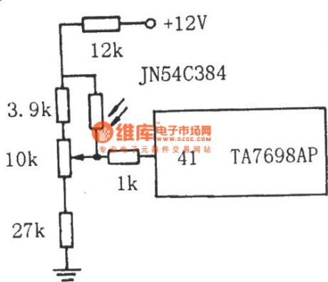
The TV auto brightness adjusting circuit composed of LDR See as the figure, the LDR is connected with the middle head of the contrast potentiometer. By the LDR feature that its resistance changes with the brightness of the rays, the LEV on the middle head of the potentiometer changes with the brightness of the rays, then by the control of decoding circuit TA7698AP, the brightness, contrast ratio and saturation of the TV change accordingly. When the rays are bright, the resistance of GR is low, and the LEV on the middle head of the potentiometer is rising. (View)
View full Circuit Diagram | Comments | Reading(1233)
The 4-channel separation amplifier composed of 4 ISO100
Published:2011/6/15 20:35:00 Author:Borg | Keyword: 4-channel, separation amplifier

View full Circuit Diagram | Comments | Reading(484)
The new bicycle charger
Published:2011/6/15 20:51:00 Author:Borg | Keyword: bicycle charger

(1)working principle: insert the three-prong plug of charger AC220V into the AC power supply outlet of the device, insert the 36v plug into the lotus hole of the device and connect the AC220V three-prong to the mains(after the above are done, no more actions are needed). When charging, just insert the charging battery hole lotus plug into the hole of the electric bicycle. Press the starting key AN, then AN-1, AN-2 and AN-3 are connected, the charger and AC220V power supply are also on; as AN-2 is on, the 2-pin and 6-pin of IC2 are connected with the earth. (View)
View full Circuit Diagram | Comments | Reading(1172)
The phone flasher
Published:2011/6/17 7:07:00 Author:Borg | Keyword: phone flasher

E.g 14 the phone flasherThe phone ring voltage makes the Neon bulb conducting, and the photocoupler U triggers SCR conducting and the bulb is glowing, see as Figure 20-14. The frequency of the ring voltage is often at 20Hz or so, and the bulb is flashing at the frequency. The the load is the bulb, C1 will be useless. If the ring or the relay, etc, are the load, C1 is used to remove the sparkle disturbance.
(View)
View full Circuit Diagram | Comments | Reading(608)
| Pages:1744/2234 At 2017411742174317441745174617471748174917501751175217531754175517561757175817591760Under 20 |
Circuit Categories
power supply circuit
Amplifier Circuit
Basic Circuit
LED and Light Circuit
Sensor Circuit
Signal Processing
Electrical Equipment Circuit
Control Circuit
Remote Control Circuit
A/D-D/A Converter Circuit
Audio Circuit
Measuring and Test Circuit
Communication Circuit
Computer-Related Circuit
555 Circuit
Automotive Circuit
Repairing Circuit