Sensor Circuit
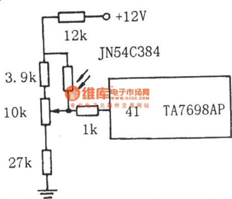
The TV auto brightness adjusting circuit composed of LDR
Published:2011/6/15 20:31:00 Author:Borg | Keyword: brightness adjusting circuit | From:SeekIC

The TV auto brightness adjusting circuit composed of LDR See as the figure, the LDR is connected with the middle head of the contrast potentiometer. By the LDR feature that its resistance changes with the brightness of the rays, the LEV on the middle head of the potentiometer changes with the brightness of the rays, then by the control of decoding circuit TA7698AP, the brightness, contrast ratio and saturation of the TV change accordingly. When the rays are bright, the resistance of GR is low, and the LEV on the middle head of the potentiometer is rising.
Reprinted Url Of This Article:
http://www.seekic.com/circuit_diagram/Sensor_Circuit/The_TV_auto_brightness_adjusting_circuit_composed_of_LDR.html
Print this Page | Comments | Reading(3)

Article Categories
power supply circuit
Amplifier Circuit
Basic Circuit
LED and Light Circuit
Sensor Circuit
Signal Processing
Electrical Equipment Circuit
Control Circuit
Remote Control Circuit
A/D-D/A Converter Circuit
Audio Circuit
Measuring and Test Circuit
Communication Circuit
Computer-Related Circuit
555 Circuit
Automotive Circuit
Repairing Circuit
Code: