
Signal Processing
Index 116
TKIANULES
Published:2009/7/23 22:32:00 Author:Jessie
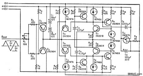
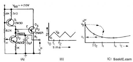
Peaks, slopes, and frequency of triangular waves can be varied independently. R10-R11 control positive slope, R11-R15 negative slope, and C1-C2 both slopes. Zener voltages of D1-D2 determine peaks.-R. Zane, Triangle Generator Adjusts Output Slopes and Peaks, Electronics, 38:12, p 85-86. (View)
View full Circuit Diagram | Comments | Reading(523)
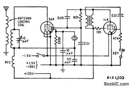
60_KC_UNDERWATER_TRANSMITTER
Published:2009/7/23 22:32:00 Author:Jessie
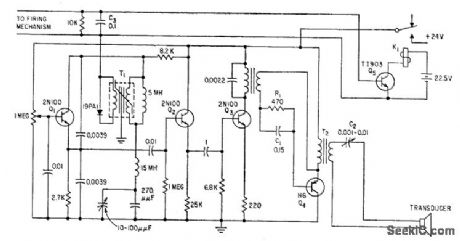
Consists of oscillator, buffer, driver, and power amplifier feeding barium titanate projector. Bandwidth is 1 kc in 60-kc region. Used to monitor underwater mine operation as test ships pass over. Receiving hydrophone on bottom may be up to 600 feet away. When mine senses approach of target, relay K1 is activated, turning on transmitter.-M. J. Aucremanne and D. D. Woolston, Telemeter System Relays Undersea Ordnance Data, Electronics, 31 :41, p 84-87. (View)
View full Circuit Diagram | Comments | Reading(656)
SYNCHRONOUS_SWEEP
Published:2009/7/23 22:31:00 Author:Jessie
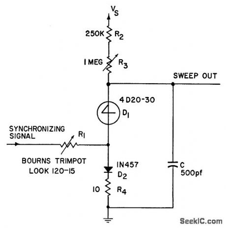
Produces linear 20-V sawtooth with four-layer diode and six other components. Maximum sweep role can reach 100 kc. Provides synchronous operation with good linearity and sufficiently Inst retrace to eliminate need for blanking in oscilloscope applications.-4-Layer Diode Sweep (Synchronous), Electronic Circuit Design Handbook, Mactier Pub. Corp., N.Y., 1965, p 173. (View)
View full Circuit Diagram | Comments | Reading(549)
02_TO_18_CPS
Published:2009/7/23 22:38:00 Author:Jessie
Provides low-frequency 5-V sweeps of high linearity, to complement conventional signal generators having maximum accuracy at higher sweeps.-A. Angelone, Subaudio Sawtooth Generator Gives One-Percent Linearity, Electronics, 34:48, p 42-43. (View)
View full Circuit Diagram | Comments | Reading(492)
RAMP_GENERATOR
Published:2009/7/23 22:36:00 Author:Jessie
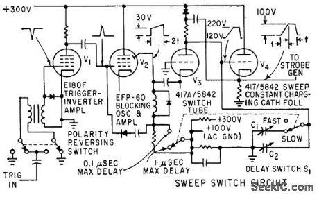

Produces positive-going ramp with 100-V amplitude when input trigger pulse is applied. Time duration of ramp can be set at 0.1 or 1 microsec. Time stability is better than 0.1 millimicrosec for long time intervals.-W. E. Bushor, Sample Method Displays Millimicrosecond Pulses, Electronics, 32:31, p 69-71. (View)
View full Circuit Diagram | Comments | Reading(0)
One_decade_low_distortion_sine_wave_generator_
Published:2009/7/23 22:54:00 Author:Jessie
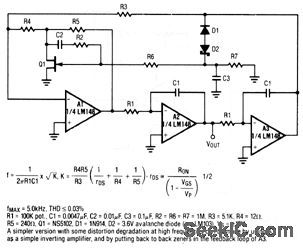
This circuit uses three sections of an LM148 op amp. The frequency of VOUT is set by R1, and is 5 kHz maximum with the values shown. Raytheon Linear Integrated Circuts, 1989, p. 4-263. (View)
View full Circuit Diagram | Comments | Reading(891)
CB_WITHOUT_SEND_RECEIVE_RELAY
Published:2009/7/23 22:54:00 Author:Jessie
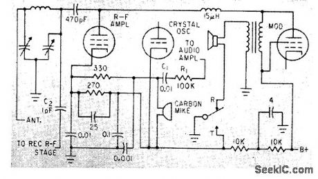
With switch in transmit position, carbon mike gets some of r-f amplifier current, and audio signals in last audio stage Heising-modulate transmitter. During reception, receiver local oscillator gets plate voltage, loudspeaker is connected, and cathodes of transmitter cry still oscillator and r-f amplifier are made positive to cut them off.-L. Solomon, Citizens Band Equipmenl Design, Electronics, 33:45, p 70-72. (View)
View full Circuit Diagram | Comments | Reading(589)
50_KC_SAWTOOTH
Published:2009/7/23 22:54:00 Author:Jessie
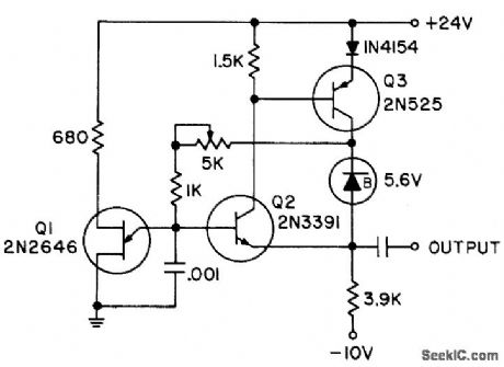
Uses bootstrap charging circuit, with constant voltage maintained across charging resistor by zener diode and emitter-follower amplifier Q3, so capacitor charging current is constant over complete cycle.- Transistor Manual, Seventh Edition, General Electric Co., 1964, p 319. (View)
View full Circuit Diagram | Comments | Reading(516)
CLASS_C_CB_TRANSMITTER
Published:2009/7/23 22:53:00 Author:Jessie
Control signal may be tone-modulated a-m, with different tones to control several functions on one frequency.-L. G. Sands, Citizens Radio Revision Spurs Equipment Design, Electronics, 32:15, p 55-57. (View)
View full Circuit Diagram | Comments | Reading(910)
LINEAR_SAWTOOTH_1
Published:2009/7/23 22:53:00 Author:Jessie
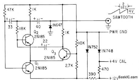
Develops signal with 4-V amplitude and 2.sec period.-O. C. Hay-cock and K. D. Baker, Measuring Antenna Impedance in 34:2, p 88-92. (View)
View full Circuit Diagram | Comments | Reading(555)
THYRATRON_SWITCH_TRANSMITTER
Published:2009/7/23 22:52:00 Author:Jessie
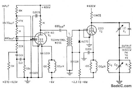
Receives 100 or 1,000-pps trigger pulse from rate generator and produces pulse of r-f oscillations that decays from maximum peak-to-peak of 300 v, for measuring ultrasonic velocity in metal test sample. Pulse litter is less than 1 millimicrosec, for accurate measurement of lime interval between ultrasonic echo pulses.-R. L. Forgacs, Removing the Jitter from Thyratron Pulses, Electronics, 32:20, p 60-61. (View)
View full Circuit Diagram | Comments | Reading(548)
CLASS_B_CB_TRANSCEIVER
Published:2009/7/23 22:52:00 Author:Jessie
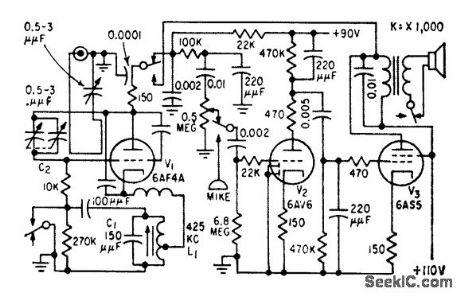
On transmit, V1 is self-excited power oscillator, V3 is am modulator, and V2 is speech amplifier. On receive, V1 is superregenerative r-f amplifier, V3 is audio power amplifier, and V2 is first audio stage.-L. G. Sands, Citizens Radio Re. vision Spurs Equipment Design, Electronics, 32:15, p 55-57. (View)
View full Circuit Diagram | Comments | Reading(948)
UJT_TRIANGULAR_WAVE_GENERATOR
Published:2009/7/23 22:51:00 Author:Jessie
Two current generators produce triangular wave by alternately charging and discharging C1.Ujt and diode serve as switch to reverse slope of ramp.-R. Dean, Unijunction Triangular Wave Generator, EEE, 12:4, p 59. (View)
View full Circuit Diagram | Comments | Reading(1986)
Low_frequency_sine_wave_generator_with_quadrature_output
Published:2009/7/23 22:51:00 Author:Jessie
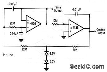
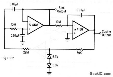
This circuit uses two sections of a 4136 op amp. The frequency of both the sine and cosine output is 1 Hz with the values shown. Raytheon Linear Integrated Circuits, 1989, p. 4-173. (View)
View full Circuit Diagram | Comments | Reading(949)
NOISE_ACTUATED_AVC
Published:2009/7/23 22:50:00 Author:Jessie
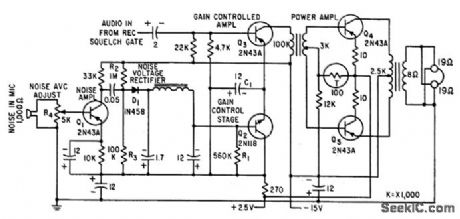
Emitter current of 2N43A controlled low-level audio amplifier stage Q3 is regulated indirectly by sound pressure level of ambient noise. With no noise, gain of controlled amplifier is prevented front going to zero by applying quiescent conduction bias through R1 to gain-control stage Q2.-D. C. Gibson, Helmet Transceiver for Flight Deck Communications, Electronics, 33:39, p 56-60. (View)
View full Circuit Diagram | Comments | Reading(497)
SIMPLE_UJT_SWEEP
Published:2009/7/23 22:50:00 Author:Jessie
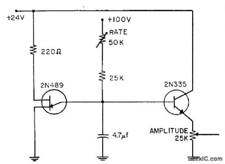
Generates variable-frequency sawtooth directly, with emitter-follower 2N335 serving only for isolation. Sawtooth frequency can be varied without affecting output amplitude.-Unijunction Sweep, EEE, 11:7, p 86. (View)
View full Circuit Diagram | Comments | Reading(695)
Wien_bridge_oscillator
Published:2009/7/23 22:50:00 Author:Jessie
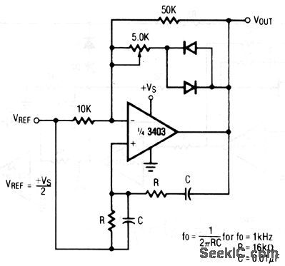
The frequency of VOUT is set by the values of R and C, as shown. Adjust the 5- kΩ potentiometer until the VREF point is one-half of the source voltage,VS. Raytheon Linear Integrated Circuts, 1989, p. 4-161. (View)
View full Circuit Diagram | Comments | Reading(1588)
THREE_TRANSISTOR_CB_TRANSCEIVER
Published:2009/7/23 22:50:00 Author:Jessie
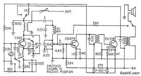
Has 30-mw r-f output and range of several thou. sand feet. Detector uses 40-kc quench. Draws 15 ma for receive and 30 ma for transmit. loudspeaker serves as microphone for transmitting.-L. Solomon, Gitizens Band Equipment Design, Electronics, 33:45, p 70-72. (View)
View full Circuit Diagram | Comments | Reading(571)
TRIANGULAR
Published:2009/7/23 22:49:00 Author:Jessie
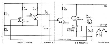
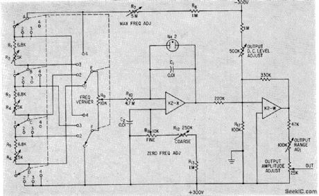
Deviation is less thon 1% from linearity at any frequency front 400 cps to 1 cycle per hour. Frequency is changed by varying R1, R2 or C; values shown give 20-second period. Used to sweep magnetic fold across air gap of electromagnet and for testing servos and vlf amplifiers.-J. r. Delpech, Triangular Waveforms Have 1 % linearity, Electronics, 38:7, p 86-87. (View)
View full Circuit Diagram | Comments | Reading(473)
Low_frequency_doubler
Published:2009/7/23 22:46:00 Author:Jessie
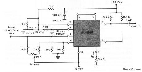
This circuit shows an MC1596 operating as a frequency doubler in the audio to 1-MHz range, with all spurious outputs greater than 30-dB below the desired 2fIN-output signals. (View)
View full Circuit Diagram | Comments | Reading(0)
| Pages:116/195 At 20101102103104105106107108109110111112113114115116117118119120Under 20 |
Circuit Categories
power supply circuit
Amplifier Circuit
Basic Circuit
LED and Light Circuit
Sensor Circuit
Signal Processing
Electrical Equipment Circuit
Control Circuit
Remote Control Circuit
A/D-D/A Converter Circuit
Audio Circuit
Measuring and Test Circuit
Communication Circuit
Computer-Related Circuit
555 Circuit
Automotive Circuit
Repairing Circuit