
Signal Processing
Index 111
NOISE_SQUELCH
Published:2009/7/23 23:00:00 Author:Jessie
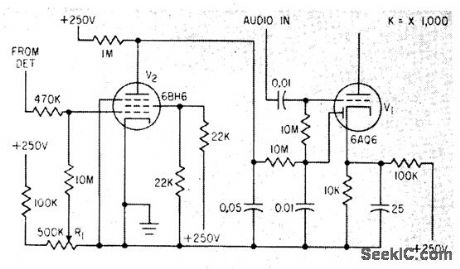
When negative-going signal is received from detector, control grid of squelch tube V2 goes negative until positive bitts set by squelch control R1 is overcome. Used in Vocaline CB transceiver.-L. Solomon, Citizens Band Equipment Design, Electronics, 33:45, p 70-72. (View)
View full Circuit Diagram | Comments | Reading(1017)
NAND_GATE_TIL_CRYSTAL
Published:2009/7/6 0:40:00 Author:May

Overcomes problems of poor starting performance and has upper frequency limit of 20 MHz. Suitable for applications requiring high-output aperiodic oscillator. Excellent as frequency marker.-R. Harrison, Survey of Crystal Oscillators, Ham Radio, March 1976, p 10-22. (View)
View full Circuit Diagram | Comments | Reading(2565)
CB_DECODER
Published:2009/7/23 22:59:00 Author:Jessie

Responds to telephone-dialdigital tone pulses from receiver. Rejects noise pulses and functions even when noise is stronger than desired single-tone signal. Used in mobile dial telephones.-L. G. Sands, Citizens Radio Revision Spurs Equipment Design, Electronics, 32:15, p 55-57. (View)
View full Circuit Diagram | Comments | Reading(573)
2_20_MHz_VXO
Published:2009/7/6 0:40:00 Author:May

Variable-frequency crystal oscillator plus buffer, using Signetics N7404A hex inverter or equivalent, covers 2-20 MHz. Only three inverters are used, two forming oscillator and one as output buffer. VCC is +5 V. Crystals can operate at fundamental, third, or fifth over-tone. Frequency-limiting capacitor Cp can be 15 pF. Only higher-frequency crystals can be moved useful amounts without creating instability problems. Article gives design equations and tables showing frequencies obtained with various crystals for various values of frequency controls CV (0-100 pF) and LV (0-17 μH).-B. King, Hex Inverter VXO Circuit, Ham Radio, April 1975, p 50-55. (View)
View full Circuit Diagram | Comments | Reading(2655)
90_125_MHz_CRYSTAL
Published:2009/7/6 0:39:00 Author:May

Recmmended for VHF/UHF converters. Output is 5 to 15 mW. Crystal should be high-quality fifth- or seventh-over-tone type. Ferrite bead FB prevents undesired oscillation above 500 MHz. For best stability, allow crystal to operate at its natural series-resonant frequency and use regulated power supply.-J. Reisert, VHF/UHF Techniques, Ham Radio, March 1976, p 44-48. (View)
View full Circuit Diagram | Comments | Reading(870)
50_1000_kHz
Published:2009/7/6 0:36:00 Author:May

Simple single-transistor circuit provides extremely stable beat-frequency oscillator for which frequency can be changed by using tank-circuit components listed in table.-Circuits, 73 Magazine, Feb. 1974, p 101. (View)
View full Circuit Diagram | Comments | Reading(1834)
1_2_kHz_TONE_GENERATOR
Published:2009/7/6 0:35:00 Author:May
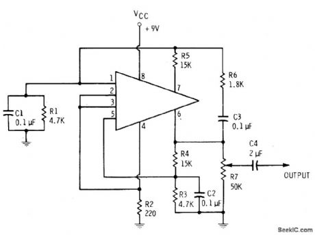
Simple feedback circuit converts HEP 580 IC to emitter-coupled MVBR producing reasonably sinusoidal output somewhere between 1 and 2 kHz. Supply is 9-V battery.-E. M. Noll, Linear IC Principles, Experiments, and Projects, Howard W. Sams, Indianapolis, IN, 1974, p 64-65. (View)
View full Circuit Diagram | Comments | Reading(1075)
150_500_kHz_CRYSTAL
Published:2009/7/6 0:35:00 Author:May

Circuit is series-mode if C1 is 0.01 μF. Parallel-mode crystals can be used if C1 is equal to specified load capacitance (30, 50, or 100 pF) for crystal. Harmonic output is usually better than -30 dB. Circuit is particularly good for crystals prone to oscillate undesirably at twice fundamental frequency. L1 is 800-2000 μH for 150-300 kHz, and 360-1000 μH for 300-500 kHz. Adjusting slug in L1 pulls crystal frequency. Q1 is 2N3563, 2N3564, 2N3693, BC107, BC547, or SE1010.-R. Harrison, Survey of Crystal Oscillators, Ham Radio, March 1976, p 10-22. (View)
View full Circuit Diagram | Comments | Reading(887)
STEPPER_MOTOR_TESTER
Published:2009/7/23 21:47:00 Author:Jessie
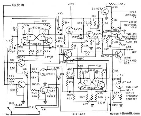
Digital test equipment automatically evaluates performance of magnetically detented stepper motors in several modes, for wide variety of test conditions. Analyzer compares number of applied voltage steps with number of motor movements. Pulse train from power amplifier is gated through logic circuits that pre vent switching from occurring in middle of pulse, and keep input pulse line closed even when switching motor direction.-H. J. Weber and M. Weiss, Analyzing Magnetically-De-tented Stepper Servo Motors, Electronics, 33:39, p 71-74. (View)
View full Circuit Diagram | Comments | Reading(923)
WIEN_SINE_WAVE
Published:2009/7/5 23:53:00 Author:May

Uses NE571 analog compandor in oscillator circuit based on Wien network formed by R1-C1 and R2-C2, placed around output amplifier of section A to make it bandpass amplifier. Section B serves as inverting amplifier with nominal gain of 2. Total harmonic distortion is below 0.1%. Operating frequency is about 1.6 kHz for values shown, but can be varied from 10 Hz to 10 kHz. Frequency is l/21πRCforR = R1 = R2 and C = Cl = C2. R should be kept between 10K and 1 megohm and C between 1000 pF and 1 μF. Useful as fixed-frequency oscillator but can be tuned if matched dual pot is used for R1.R2.-W. G. Jung, Gain Control IC for Audio Signal Processing. Ham Radio, July 1977, p 47-S3. (View)
View full Circuit Diagram | Comments | Reading(1221)
TUNNEL_DIODE_TESTER
Published:2009/7/23 22:02:00 Author:Jessie

Curve-tracing circuit provides cro traces as aid in determining proper bias and circuit impedances for operating tunnel diode as switch, amplifier, or oscillator.-R. P. Murray, Biasing Methods for Tunnel Diodes, Electronics, 33:23, p 82-83. (View)
View full Circuit Diagram | Comments | Reading(733)
SING_AROUND_TRANSMITTER
Published:2009/7/23 22:02:00 Author:Jessie

Used for precision measurement of ultrasonic velocity in liquids and solids. Transmit pulse is applied to ultrasonic transducer on one side of sample. Receiving transducer on other side generates signal to retrigger transmitter,with process repeating in sing-around fashion. Time and number of sing-around cycles are measured to get velocity.-R. L. Forgacs, Precision Ultrasonic Velocity Measurements, Electronics, 33:47, p 98-100. (View)
View full Circuit Diagram | Comments | Reading(646)
PULSE_GENERATOR(ASTABLE_MULTIVIBRATOR)
Published:2009/7/5 23:42:00 Author:May
Circuit Notes
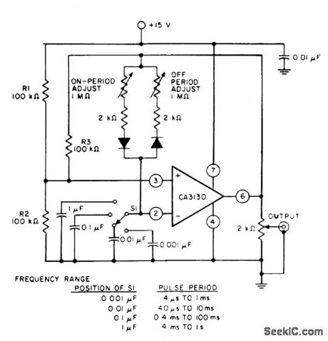
Resistors R1 and R2 bias the CA3130 to the mid-point of the supply-voltage, and R3 is the feedback resistor. The pulse repetition rate is selected by positioning S1 to the desired position and the rate remains essentially constant when the resistors which determine on-period and off-period are adjusted. (View)
View full Circuit Diagram | Comments | Reading(983)
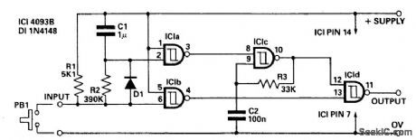
DELAYED_PULSE_GENERATOR
Published:2009/7/5 23:37:00 Author:May
Circuit Notes
The circuit offers independent control of initial delay and pulse rate. IC1c is connected as a pulse generator whose operation is inhibited by the normally low O/P of the IC1a.When the circuit input goes low i.e., by pressing PB1, IC1b O/P goes high and the circuit O/P goes low thus replicating the input. When the input is kept low capacitor C1 charges via R2 to a point where IC1a O/P goes low. This allows the pulse generator IClc to start and rapid fire pulses appear at the circuit O/P. When the circuit input returns to the high state C1 is rapiD1y discharged via D1 and R1. The value of R2 and C1 control the initial delay while R3 and C2 control the pulse rate. The values given will give a delay of around 0.5 seconds and a pulse rate of 200/300 Hz depending on supply voltage. PB1 may be replaced by an open collector TTL gate or a common emitter transistor stage if required. (View)
View full Circuit Diagram | Comments | Reading(0)
200_65000_Hz_WlEN
Published:2009/7/5 23:34:00 Author:May
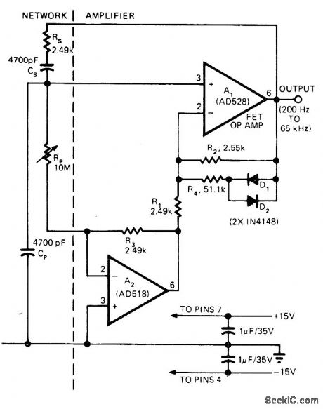
Adding single opamp to Wien-bridge oscillator gives wide-range oscillatorhaving single-control tuning. R4, D1, and D2 together stabilize output amplitude by providing controlled nonlinearity that reduces gain at high signal Ievels. AD528 opamp A1 is FET-input complement to AD518 A2 and has bandwidth required for wide output frequency range.RP sweeps output from 200 Hz to 65 kHz. Since oscillation frequency is inversely proportional to square root of RP, frequency changes rapidly near Iow-resistance end of pot. Use of pot with audio or Iog taper makes tuning more Iinear.-P. Brokaw, FET Op Amp Adds New Twist to an Old Circuit. EDN Magazine. June 5. 1974. p 75-77. (View)
View full Circuit Diagram | Comments | Reading(702)
20_Hz_TO_200_kHz
Published:2009/7/5 23:27:00 Author:May

Variable-frequency RC-tuned oscillator uses FETs with Wien-bridge frequency-determining network, Identical resistors accurateto at Ieast 1% are switched in pairs to change range. Dual 365-pF variable capacitor C2 is used for tuning in each range. Can be calibrated against standard audio frequency with CRO set up for Lissajous figures, or calibrated with high-precision AF meter connected to AF output terminals.-R. P. Turner, FET Circuits, Howard W. Sams, Indianapolis, IN, 1977, 2nd Ed., p 132-134. (View)
View full Circuit Diagram | Comments | Reading(1704)
NEGATlVE_RESISTANCE_LED_OSCILLATOR
Published:2009/7/5 23:04:00 Author:May

Covers frequency range of about 3.2-8 kHz with values shown. WilI drive Ioudspeaker inserted at point X. For lower frequency (range of 120-1800 Hz) and Iouder sound, change C1 to 1 μF.Negative-resistance portion of circuit indudes Q1, Q2, LED, R2, and R3. Optoisolator can be MCT-2 or equivalent.-F. M, Mims, Electronic Circuitbook 5: LED Projects, Howard W. Sams, Indianapolis, IN, 1976, p 26-29. (View)
View full Circuit Diagram | Comments | Reading(778)
TRANSISTOR_GAIN_AND_LEAKAGE_TESTER
Published:2009/7/23 21:52:00 Author:Jessie

Designed for general testing of production units. Switch S1 changes over from npn to pnp transistors. After controls are set for a specific transistor type, checking involves only noting base current when lest button is, pressed.-F. W. Kear, Simple Test for Transistor Quality, Electronics, 35:39, p 80-81. (View)
View full Circuit Diagram | Comments | Reading(704)
CAPACITIVELY_TUNED_TUNNEL_DIODE_TUNER_
Published:2009/7/23 21:50:00 Author:Jessie

Uses self-oscillating tunnel-diode converter circuit.- Transistor Manual, Seventh Edition, General Electric Co., 1964, p 359. (View)
View full Circuit Diagram | Comments | Reading(623)
WIDE_ARNGE_VARIABLE_OSCILLATOR
Published:2009/7/5 22:59:00 Author:May

View full Circuit Diagram | Comments | Reading(629)
| Pages:111/195 At 20101102103104105106107108109110111112113114115116117118119120Under 20 |
Circuit Categories
power supply circuit
Amplifier Circuit
Basic Circuit
LED and Light Circuit
Sensor Circuit
Signal Processing
Electrical Equipment Circuit
Control Circuit
Remote Control Circuit
A/D-D/A Converter Circuit
Audio Circuit
Measuring and Test Circuit
Communication Circuit
Computer-Related Circuit
555 Circuit
Automotive Circuit
Repairing Circuit