
Signal Processing
Index 113
FREQUENCY_DIVIDER_AND_STAIRCASE_GENERATOR
Published:2009/7/5 22:32:00 Author:May

View full Circuit Diagram | Comments | Reading(2389)
WIDE_RANGE_VARIABLE_OSCILLATOR
Published:2009/7/5 22:31:00 Author:May

View full Circuit Diagram | Comments | Reading(660)
OSCILIATOR_WITH_QUADRATURE_OUTPUT
Published:2009/7/5 22:30:00 Author:May

View full Circuit Diagram | Comments | Reading(663)
PRECISION_OSCILLATOR_WITH_20_NS_SWITCHING
Published:2009/7/5 22:30:00 Author:May

View full Circuit Diagram | Comments | Reading(634)
FUNCTION_GENERATORI_
Published:2009/7/5 22:27:00 Author:May
View full Circuit Diagram | Comments | Reading(471)
EXPONENTIAL_DIGITALLY_CONTROLLED_OSCILLATOR
Published:2009/7/5 22:27:00 Author:May


The microprocessor-controlled oscillator has a 8159 to 1 frequency range covering 2.5 Hz to 20 kHz. An exponential, current output IC DAC functioning as a programmable current source alternately charges and discharges capacitor between precisely-controlled upper and lower limits. The circuit features instan-taneous frequency change, operates with +5 ±1 V and -15 V ±3 V supplies, and has the dynamic range of a 13-bit DAC. (View)
View full Circuit Diagram | Comments | Reading(764)
GATED_OSCILLATOR
Published:2009/7/5 22:24:00 Author:May

View full Circuit Diagram | Comments | Reading(0)
TRANSISTOR_TEST_CIRCUIT
Published:2009/7/23 22:07:00 Author:Jessie
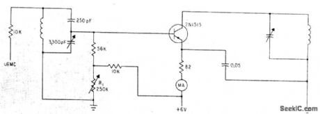
Measures power gain, with emitter current varied manually by R1 in base circuit. Used to determine conditions for uniform emitter current, required for uniform gain in transistor circuits despite variations in d-c beta values of transistors.-K. Redmond, Biasing Transistors for Uniform Gain, Electronics, 33:50, p 74-75. (View)
View full Circuit Diagram | Comments | Reading(649)
Low_power_SSB_generator
Published:2009/7/23 22:07:00 Author:Jessie
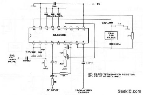
This circuit shows an SL6700 (Fig. 2-13) connected to form a low-power no-adjustment SSB generator. Notice that the microphone input is applied directly to the SL6700. Although this does not provide the same SSB quality as that of the Fig. 2-23 circuit, the savings in components and lower power consumption make the Fig.2-24 circuit attractive for hand-held CB, manpacks,etc. (View)
View full Circuit Diagram | Comments | Reading(1557)
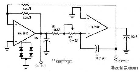
VARIABLE_AUDIO_OSCILLATOR,20_Hz_TO_20_kHz
Published:2009/7/5 22:23:00 Author:May

To obtain a 1000:1 Sweep Range, the vol-tage across external resistors RA and RB must decrease to nearly zero. This requires that the highest voltage on control pin 8 exceed the voltage at the top of RA and RB by a few hundred millivolts. The circuit achieves this by using a diode to lower the effective supply voltage on the 8038. The large resistor on pin 5 helps reduce duty cycle variations with sweep. (View)
View full Circuit Diagram | Comments | Reading(838)
50_kHz_OSCILLATOR
Published:2009/7/5 22:21:00 Author:May


A 50 kHz circuit is possible becasuse of the more nearly ideal characteristics of the D5K. (View)
View full Circuit Diagram | Comments | Reading(922)
10_kHz_OSCILLATOR
Published:2009/7/5 22:20:00 Author:May

The capacitor charges until switching vol-tage is reached. When SUS switches on, the inductor causes current to ring. When the cur-rent thru SUS drops below the holding current, the device turns off and the cycle repeats. (View)
View full Circuit Diagram | Comments | Reading(706)
350_Hz_STABILIZED_SINE_WAVE
Published:2009/7/5 22:20:00 Author:May

Squarewave oscillator Q2-Q3 stabilized by Q1, followed by passive filter and active filter using μA709, produces amplitude-stabilized sine wave at 350 Hz, for which third harmonic is 39 dB down and other harmonics are insignificant.-E. Neugroschel and A. Paterson, Amplitude-Stabilized Audio Oscillator, EEE Magazine, April 1971, p 65. (View)
View full Circuit Diagram | Comments | Reading(577)
25_Hz_SINE_WAVE
Published:2009/7/5 22:14:00 Author:May

Output voltage is 8 V P-P at about 25 Hz for values shown, with total harmonic distortion less than 0.5%. Circuit will operate from 15 Hz to 100 kHz by using other values. Set regeneration control Rl, at minimum value needed to sustain oscillation.-J. C. Freebom, Simple Sinewave Oscillator, EDN/EEE Magazine, Sept. 1, 1971, p44. (View)
View full Circuit Diagram | Comments | Reading(770)
DOT_GENERATOR
Published:2009/7/5 22:07:00 Author:May
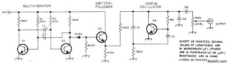
Can be used by amateur radio operator to talk himself onto frequency while Iistening on downlink passband of Oscar satellite, without causing interference to other stations using satellite. Generates audio dots at rate of 12 per second. Frequency of free-running MVBR Q1-Q2 is determined by values of C1, C2, R1, and R2. Emitter-follower Q3 drives 1500-Hz audio oscillator Q4. C1 and C2 are 1-μF 16-V electrolytics. Q1-Q4 are 2N2222 or equivalent NPN general-purpose transistors.-M. Righini and G. Emiliani. Audio Dot Generator Eases OSCAR SSB Spotting, QST, Nov. 1977. p 45. (View)
View full Circuit Diagram | Comments | Reading(577)
38_kHz
Published:2009/7/5 21:40:00 Author:May

Simple opamp circuit provides convenient sine-wave AF signal.-J. s. Lucas. Unusual Sinewave Generator.Wireless World. May 1977.p 81 (View)
View full Circuit Diagram | Comments | Reading(2691)
TV_CONTROL_RECEIVER
Published:2009/7/23 22:10:00 Author:Jessie
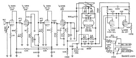
Uses barium titanate transducer as microphone, tuned with 20-mh coil to provide peaks at control frequencies of 38.5 and 41.5 kc. Balanced discriminator detects the two ultrasonic tones. Frequency shift of continuous ultrasonic tone activates tuning-motor relay. Both audio and video are killed during tuning. Also provides remote on. off control of power.-N, Frihart and J. Krakora, Ultrasonic Tones Select Tv Channels, Electronics, 31:23, p 68-69. (View)
View full Circuit Diagram | Comments | Reading(1229)
CW_IF_strip
Published:2009/7/23 22:10:00 Author:Jessie
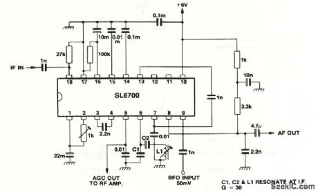
This circuit shows an SL6700 (Fig.2-13)connected to form a CW IF strip with minimum component count,and no ceramlc filter. (View)
View full Circuit Diagram | Comments | Reading(787)
LOW_COST_ULTRA_HIGH_VOLTAGE_GENERATOR
Published:2009/7/5 21:34:00 Author:May
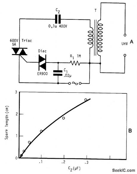
Circuit NotesBy repetitively charging and discharging a capacitor through the primary of an induction coil with a high voltage, an ultra high emf is induced in the secondary. Switching is performed by the triac, triggered by the disc at times set by C1 and R1. With a 12 V car ignition coil for example, the length of sparkgap obtained is 12 mm of air for C2 = 0.1μF. If the dielectric strength of air is assumed to be 3 kV/mm, this spark-gap length corresponds to 36 kV. From the curve shown in Fig. B, care must be taken in keeping the value of C2 below 1μF as the coil is liable to be seriously damaged at this value of C2. Power consumption is only about one watt. (View)
View full Circuit Diagram | Comments | Reading(0)
Remote_control_recetver
Published:2009/7/23 22:09:00 Author:Jessie
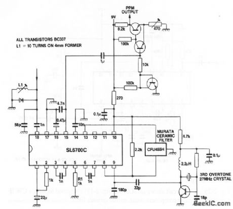
This circuit shows an SL6700 (Fig. 2-13) used as a complete 27-MHz remote-control receiver (such as used for most model controls). (View)
View full Circuit Diagram | Comments | Reading(1542)
| Pages:113/195 At 20101102103104105106107108109110111112113114115116117118119120Under 20 |
Circuit Categories
power supply circuit
Amplifier Circuit
Basic Circuit
LED and Light Circuit
Sensor Circuit
Signal Processing
Electrical Equipment Circuit
Control Circuit
Remote Control Circuit
A/D-D/A Converter Circuit
Audio Circuit
Measuring and Test Circuit
Communication Circuit
Computer-Related Circuit
555 Circuit
Automotive Circuit
Repairing Circuit