
Signal Processing
Index 117
CB_FILTER
Published:2009/7/23 22:46:00 Author:Jessie
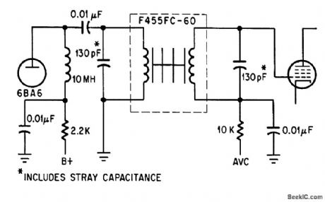
Electromechanical filler with 6-kc bandwidth at 455 kc gives 8 db signal-to-noise improvement.-Filtering the Chatter on Citizens' Band, Electronics, 38:5, p 81. (View)
View full Circuit Diagram | Comments | Reading(583)
Quadrature_oscillator
Published:2009/7/23 22:46:00 Author:Jessie
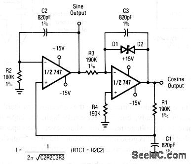
This circuit uses both sections of a 747 op amp. The frequency of the sine and cosine output is set by the values of R3, C3, R2, and C2, as shown. Raytheon Linear Integrated Circuits, 1989, p. 4-148. (View)
View full Circuit Diagram | Comments | Reading(810)
POSITIVE_OR_NEGATIVE_SLOPE
Published:2009/7/23 22:45:00 Author:Jessie
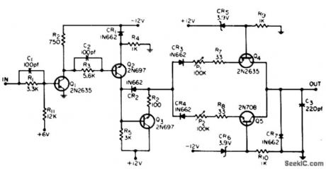
Generates linear ramps, either negative or positive, by switching two current sources on and off during charging of C3.-G. Marosi, Positive or Negative Slope Generator, EEE, 13:5, p 43. (View)
View full Circuit Diagram | Comments | Reading(670)
UNDERSEA_PROPAGATION_GATE_GENERATORS
Published:2009/7/23 22:44:00 Author:Jessie
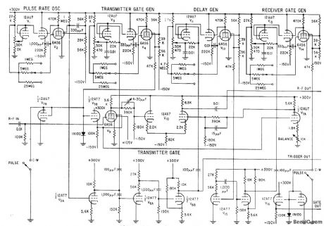
Pulse-rate oscillator V1 generates pulses with variable lime interval from 0.3 to 170 millisec for triggering rate. Normal operation is at 80 millisec, corresponding to 12.5 cps. Trigger pulses are amplified and delivered to circuits that trigger transmitter and delay generators for two receivers, and synchronize cm sweep. Used to measure changes in propagation time of less than 20 microsec over direct path of up to 300 feet in sea water.-W. C. Gore, Ultrasonics Tests Undersea Propagation, Electronics, 31:35, p 32-35. (View)
View full Circuit Diagram | Comments | Reading(572)
SIMPLE_SUBAUDIO_SWEEP
Published:2009/7/23 22:44:00 Author:Jessie
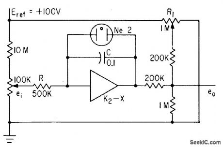
Uses operational amplifier in integrating circuit, neon lamp as automatic switch, and resistance network that allows output to be varied around level set by R1. Used to generate sweeps with high linearity up to 18 cps.-A. Angelone, Subaudio Sawtooth Generator Gives One-Percent linearity, Electronics, 34:48, p 42-43. (View)
View full Circuit Diagram | Comments | Reading(575)
CB
Published:2009/7/23 23:01:00 Author:Jessie
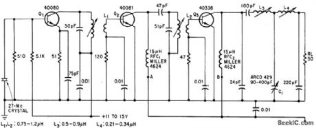
Three overlay transistors provide5 w for 27-Mc citizens-band a-m transmitter.-D. J. Donahue and B. A. Jacoby, Putting the Overlay to Work at High Frequencies, Electronics, 38:17, p 78-81.
(View)
View full Circuit Diagram | Comments | Reading(825)
DIODE_SWITCHED_CRYSTALS
Published:2009/7/3 4:11:00 Author:May

1N458 diodes switch crystals in pairs to provide two different degrees of selectivity for 455-kHz IF filter, For 500-Hz bandwidth in amateur communication receiver, spacing between crystal frequencies should be 300 Hz, which is obtained with 455.150 kHz for Y1A and 454.850 kHz for Y1B.Provides adequate CW selectivity for transceiver having good SSB filter.-J. J. Schultz, Economical Diode-Switched Crystal Filters, CQ, July 1978, p 33-35 and 91.
(View)
View full Circuit Diagram | Comments | Reading(738)
LIGHT_SENSITIVE_OSCILLATOR
Published:2009/7/3 2:39:00 Author:May

Uses 555 timer connected so frequency increases directly with intensity of light. Free-running frequency and duty cycle of timer operating in astable mode are controlled by two resistors and one capacitor. R3 sets upper frequency limit at about 6.5 kHz, and dark resistance of photocell R2 sets lower limit at about 1 Hz. Loudspeaker provides audio output, while LED flashes for visual indication when frequency goes below about 12 Hz.Applications include detection of lightning flashes, use as optical radar for blind, and use as sunrise alarm.-C. R. Graf, Build a Light Sensitive Audio Oscillator, EDN Magazine, Aug. 5, 1976, p 83. (View)
View full Circuit Diagram | Comments | Reading(1206)
LOW_COST_ULTRA_HIGH_VOLTAGE_GENERATOR
Published:2009/7/3 2:32:00 Author:May
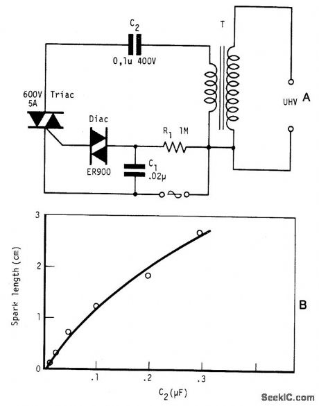
Circuit NotesBy repetitively charging and discharging a capacitor through the primary of an induction coil with a high voltage, an ultra high emf is induced in the secondary. Switching is performed by the triac, triggered by the disc at times set by C1 and R1. With a 12 V car ignition coil for example, the length of sparkgap obtained is 12 mm of air for C2 = 0.1μF. If the dielectric strength of air is assumed to be 3 kV/mm, this spark-gap length corresponds to 36 kV. From the curve shown in Fig. B, care must be taken in keeping the value of C2 below 1μF as the coil is liable to be seriously damaged at this value of C2. Power consumption is only about one watt. (View)
View full Circuit Diagram | Comments | Reading(1420)
Magnetic_speed_switch_signal_conditioner
Published:2009/7/24 4:03:00 Author:Jessie
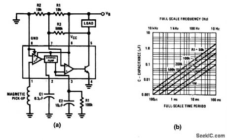
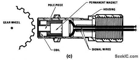
Fig. 14-17 This circuit uses an LM2907 as a signal conditioner for a magnetic speed switch, where the load is energized only when the input frequency exceeds a value set by R1 and C1. A typical example is an anti-pollution device included on recent automobiles. The device disables the vacuum-advance function until a certain speed is attained. A typical automotive pickup (Fig. 14-17C) provides 1000 pulses per mile so that, at 60 mph, the incoming frequency is 16.6 Hz. If the reference level is set by two equal resistors, R1 and R2, then the desired value of C1 and R1can be found from the equation VCC/2 VCC x C1 x R1 x f,C1R1f 0.5, and C1R1=0.03. From the RC selection chart (Fig. 1417B) choose suitable values for C1 and R1 (0.3 μF and 100 kΩ, for example). The circuit will then switch (load energized) at about 60 mph. National Semiconductor Linear Applications Handb00k 1990 p. 427. (View)
View full Circuit Diagram | Comments | Reading(1686)
16_BIT_WORD_GENERATOR
Published:2009/7/24 2:34:00 Author:Jessie
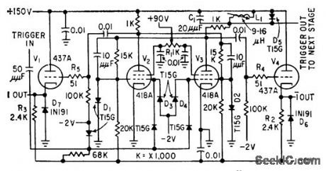
Provides all possible 16-bit serial binary words at 10-Mc rate, to simulate expected input of high-speed computer circuits. Four identical binary stages are used in word generator. Speed is derived from high-transconductance tetrodes.-R. G. Norquist, Testing High-Speed Digital Computer Circuits, Electronics, 32:29, p 50-51. (View)
View full Circuit Diagram | Comments | Reading(751)
BINARY_TONE_GENERATOR_FOR_BLIND
Published:2009/7/3 2:05:00 Author:May
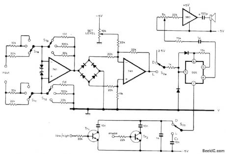
When low/high input is voltage in binary form, as obtained from converter circuit (also given in artide) fed by digital voltmeter, circuit produces Iow pitch for binary 0 and high pitch for binary 1 when S2 is set at D for digital voltmeter mode. Recognition of binary digits in tone form can be leamed by blind person much as leaming of Morse code. Uses LM566 IC as tone-generating VCO that feeds loudspeaker through LM380 IC amplifier and 5K volume control. With S2 at position L, circuit serves as audio null detector for bridge connected to input terminals; S1 is used to increase sensitivity of 741 opamp as null is approached. Article covers operation of circuits in detail.-R. A. Hoare, An Audible Voltmeter and Bridge-Indicator, Wireless World, Sept.1976, p 87-89. (View)
View full Circuit Diagram | Comments | Reading(1672)
LOW_COST_HIGH_FREQUENCY_GENERATOR
Published:2009/7/2 21:31:00 Author:May
View full Circuit Diagram | Comments | Reading(553)
STROBE_TONE_BURST_GENERATOR
Published:2009/7/2 21:30:00 Author:May

With a dual supply voltage, the external capacitor on pin 10 can be shorted to ground to halt the 8038 oscillation. The circuit uses a FET switch and diode ANDed with an input strobe signal to allow the output to always start on the same slope. (View)
View full Circuit Diagram | Comments | Reading(0)
100_kHz_QUADRATURE_OSCILLATOR
Published:2009/7/2 21:27:00 Author:May

View full Circuit Diagram | Comments | Reading(664)
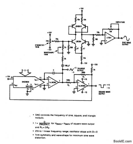
PROGRAMMED_FUNCTION_GENERATOR
Published:2009/7/2 21:21:00 Author:May
View full Circuit Diagram | Comments | Reading(588)
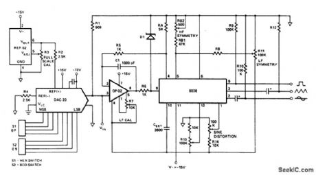
DAC_CONTROLLED_FUNCTION_GENERATOR
Published:2009/7/2 21:18:00 Author:May
View full Circuit Diagram | Comments | Reading(589)
LOW_COST_ADJUSTABLE_FUNCTION_GENERATOR
Published:2009/7/2 20:45:00 Author:May

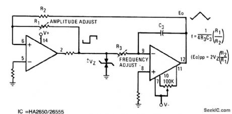
This low-cost operational-amplifier circuit (A) generates four different functions with adjustable periods. For the components shown here, the period of the output waveforms is given by T = 4RC and T = 2RC. With switch S1 in position A,V1 is a triangular waveform,while V2 is a square wave (B). With the switch in position B,a sawtooth waveform is generated at V1 and a pulse at V2 (C). (View)
View full Circuit Diagram | Comments | Reading(651)
TONE_TIMBRE_DEMONSTRATOR
Published:2009/7/24 2:08:00 Author:Jessie
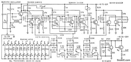
Demon-strates principles of Fourier synthesis of musical tone, for one octave. Lowest fundamental is 250 cps. Switches S1, S2, and S3 add or remove third harmonic, second harmonic, or fundamental components from out put signal to change tone quality. Master oscillator has range of 1.5 to 3 kc. Blocking oscillator Q1 is tuned through one octave by varying voltage to which R4 is returned, by switching resistors in series with playing keys.-W. S. Pike and C. N. Hoyler, Synthesizing Timbre for Electronic Musical Tones, Electronics, 32:22, p 92-94. (View)
View full Circuit Diagram | Comments | Reading(538)
CMOS_INTERFACE_USING_OPTOlSOLATOR
Published:2009/7/2 20:18:00 Author:May

Provides logic control of 350-mA lamp. High level on input of typical CMOS inverter energizes 4N25 optoisolator, to clamp Q1 off. This removes drive from Q2, deenergizing load.Logic 0 at input reverses conditions, tuming on lamp. With values shown, 10 mA at optoisolator input controls completely isolated 350-mA load.-A. Pshaenich, Interface Techniques Between lndustrial Logic and Power Devices, Motorola, Phoenix, AZ, 1975, AN-712A, p 16. (View)
View full Circuit Diagram | Comments | Reading(2155)
| Pages:117/195 At 20101102103104105106107108109110111112113114115116117118119120Under 20 |
Circuit Categories
power supply circuit
Amplifier Circuit
Basic Circuit
LED and Light Circuit
Sensor Circuit
Signal Processing
Electrical Equipment Circuit
Control Circuit
Remote Control Circuit
A/D-D/A Converter Circuit
Audio Circuit
Measuring and Test Circuit
Communication Circuit
Computer-Related Circuit
555 Circuit
Automotive Circuit
Repairing Circuit