Signal Processing
Magnetic_speed_switch_signal_conditioner
Published:2009/7/24 4:03:00 Author:Jessie | From:SeekIC


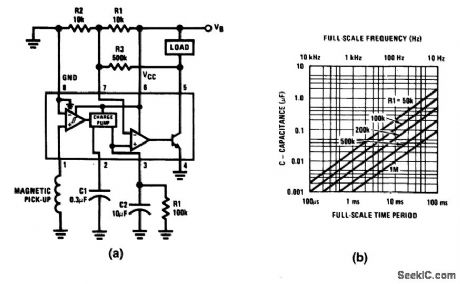
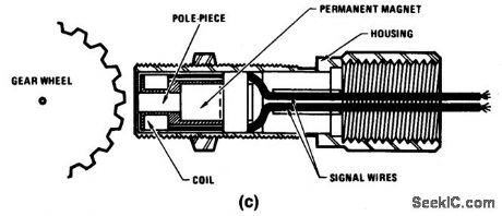
Fig. 14-17 This circuit uses an LM2907 as a signal conditioner for a magnetic speed switch, where the load is energized only when the input frequency exceeds a value set by R1 and C1. A typical example is an anti-pollution device included on recent automobiles. The device disables the vacuum-advance function until a certain speed is attained. A typical automotive pickup (Fig. 14-17C) provides 1000 pulses per mile so that, at 60 mph, the incoming frequency is 16.6 Hz. If the reference level is set by two equal resistors, R1 and R2, then the desired value of C1 and R1can be found from the equation VCC/2 VCC x C1 x R1 x f,C1R1f 0.5, and C1R1=0.03. From the RC selection chart (Fig. 1417B) choose suitable values for C1 and R1 (0.3 μF and 100 kΩ, for example). The circuit will then switch (load energized) at about 60 mph. National Semiconductor Linear Applications Handb00k 1990 p. 427.
Reprinted Url Of This Article:
http://www.seekic.com/circuit_diagram/Signal_Processing/Magnetic_speed_switch_signal_conditioner.html
Print this Page | Comments | Reading(3)

Article Categories
power supply circuit
Amplifier Circuit
Basic Circuit
LED and Light Circuit
Sensor Circuit
Signal Processing
Electrical Equipment Circuit
Control Circuit
Remote Control Circuit
A/D-D/A Converter Circuit
Audio Circuit
Measuring and Test Circuit
Communication Circuit
Computer-Related Circuit
555 Circuit
Automotive Circuit
Repairing Circuit
Code: