
Signal Processing
Index 119
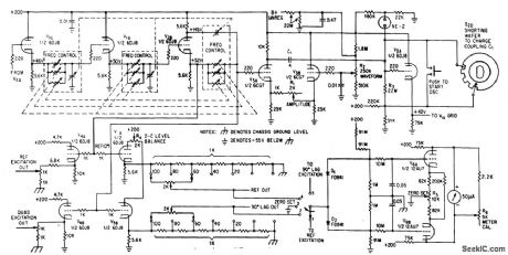
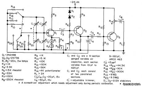
SWEEP_FREQUENCY_CLAPP_OSCILLATOR
Published:2009/7/24 2:18:00 Author:Jessie
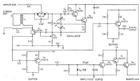
Tank circuit L1-C1-C2-C3 sweeps frequency of transistor Clapp oscillator over range of 5 to 15 Mc when current through bias winding of L1 is varied from zero to 800 ma. Collector voltage is servoed to maintain con slant output amplitude.-R. E. Daniels and A. D. Cook, Advanced Clapp Oscillator Features 3-to-1 Dynamic Range, Electronics, 36:8, p 60-61. (View)
View full Circuit Diagram | Comments | Reading(1093)
100_kHz_CPYSTAL_FET_RELAXATION
Published:2009/7/2 9:08:00 Author:May

Adding crystal in frequency-determining circuit improves frequency stabrlity of UJT relaxation oscillator. With charging capacitor replaced by 100-kHz quartz crystal, measured output frequency was 99.925 kHz. -R. D. Clement and R. L. Starliper, Crystal-Controlled Relaxation Oscillator, EDN|EEE Magazine, Oct. 15, 1971, p 62 and 64. (View)
View full Circuit Diagram | Comments | Reading(935)
CRYSTAL_COLPlTTS
Published:2009/7/2 9:05:00 Author:May

Circuit is ideal for low-frequency crystal oscillators because JFET circuit loading does not vary with temperature. Output frequency is determined by threshold used.- FET Databook, National Semiconductor, Santa Clara, CA, 1977, p 6-26-6-36. (View)
View full Circuit Diagram | Comments | Reading(1000)
8_MHz_±_5_kHz
Published:2009/7/2 9:05:00 Author:May

Tuning two-gang 365-pF variable capacitor through its range provides frequency change up to 5 kHz in output of 8-MHz crystal oscillator. L1 is 16-24 μH Miller 4507, and L2 is 40 turns No.36 tapped at 13 turns, on 1/4-inch slug-tuned form.-Circuits, 73 Magazine, Jan. 1974, p 128. (View)
View full Circuit Diagram | Comments | Reading(1039)
2255_2455_kHz_LOCAL_OSCILLATOR
Published:2009/7/2 9:04:00 Author:May

Used in 1.8-2 MHz communication receiver having wide dynamic range. Oscillator has good stability, with circuit noise at least 90 dB below fundamental output. Amplifier Q14 provides required +7 dBm for in jection into balanced mixer of receiver. Two-part article gives all other circuits of receiver.-D. DeMaw, His Eminence-the Receiver, QST, Part 1-June 1976, p 27-30 (Part 2-July 1976, p 14-17). (View)
View full Circuit Diagram | Comments | Reading(854)
5_MHz_±_250_kHz
Published:2009/7/2 9:03:00 Author:May
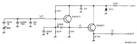
Simple and stable circuit using PNP transistors has tuning range of about 250 kHz in any segment of 5-9 MHz range, depending on how oscillator coil is set. Wind coil on ceramic form or use air-wound coil. Capacitors marked M should be mica for stability. Tuning capacitor is 365 pF,from AM radio, 400/N750 temperature-compensating capacitor can be replaced by 400-pF mica unless VFO is used in mobile application.-An Accessory VFO-the Easy Way, 73 Magazine, Aug. 1975, p 103 and 106-108. (View)
View full Circuit Diagram | Comments | Reading(694)
VARIABLE_CRYSTAL
Published:2009/7/2 9:02:00 Author:May

Maximum frequency shift is almost 10 kHz at 5 MHz. Use crystal made especially for variable operation. Frequency stability is good even at extremes of shift. Use 5-20 μH for L1 with crystals from 6-15 MHz, and 20-50 μH for 3-6 MHz. Q1 is 2N3563, 2N3564, 2N5770, BC107, BC547, BF115, BF180, SE1010, or equivalent.-R. Harrison, Sulvey of Crystal Oscillators, Ham Radio, March 1976, p 10-22. (View)
View full Circuit Diagram | Comments | Reading(2248)
CORE_SENSE_AMPLIFIER
Published:2009/7/24 2:14:00 Author:Jessie
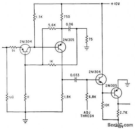
Used in programmed digital signal generator in which plug-in magnets set up program Input, nominally 100 mV, is amplified and clipped before it is gated with strobing pulse.-W. D. Woo, Novel Digital Signal Generator Uses Magnetic-Core Pegboard, Electronics, 35:27, p 46-49. (View)
View full Circuit Diagram | Comments | Reading(547)
SPECTRUM_INVARIANT_RANDOM_FUNCTION_GENERATOR
Published:2009/7/24 2:13:00 Author:Jessie
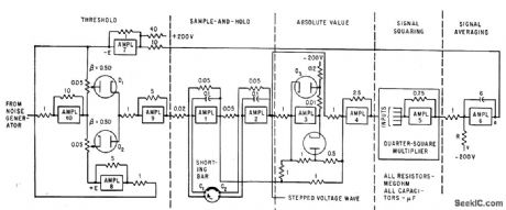
Operational amplifiers of analog computer produce periodically slopped waves by clipping and sampling raw noise signal. Feedback maintains desired power density spectrum.-N. D. Diamantides and C. E. McCray, Generating Random Forcing Functions for Control-Systems Simulation, Electronics, 34:33, p 60-63. (View)
View full Circuit Diagram | Comments | Reading(499)
01_1000_CPS_DECADE_SWITCHING_TWO_PHASE_OSCILLATOR
Published:2009/7/24 2:07:00 Author:Jessie
Simultaneous outputs at 90 deg phase difference have constant amplitudes over entire range. Direct coupling between stages avoids phase error.-Y. P. Yu, Two-Phase Oscillator Covers 0.1 to 1,000-CPS, Electronics, 36:40, p 27-29. (View)
View full Circuit Diagram | Comments | Reading(547)
COMBINED_R_F_AND_A_F_OSCILLATOR
Published:2009/7/24 2:06:00 Author:Jessie
Used for checking am receivers. Generates r-f at 0.6 Mc, determined by L1-C1, and relaxation-type audio output of 400 cps at A.-W. H. Ko, Tunnel-Diode Oscillator Delivers R-F and Audio, Electronics, 35:41, p 56. (View)
View full Circuit Diagram | Comments | Reading(494)
Programmable_DIE_DCE_transceiver
Published:2009/7/24 2:06:00 Author:Jessie
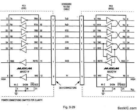
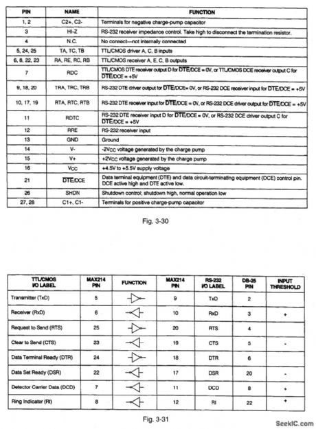
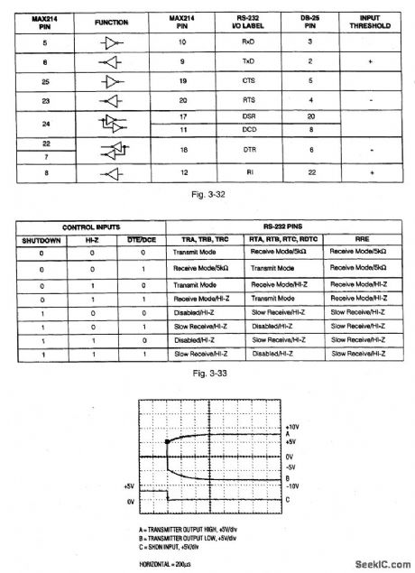
Figure 3-29 shows a typical application circuit (where two PCs have both DTE and DCE operation) for the MAX214. Figures 3-30, 3-31, 3-32, and 3-33 show the pin descriptions. Figure 3-34 shows the scope display for transmitter outputs when exiting shutdown. This IC provides a software-configurable DTE (data terminal equipment) or DCE (data circuit-terminating equipment) port RS232 interface. Either DTE or DCE is selected using the DTE/DCE pin (21). This IC eliminates the need to swap cables when switching between DTE and DCE configurations. MAXIM NEW RELEASES DATA BOOK, 1995, P, 2-69, 2-70, 2-72, 2-73, 2-74.
(View)
View full Circuit Diagram | Comments | Reading(690)
FET_WIEN_BRIDGE_OSCILLATOR
Published:2009/7/24 2:06:00 Author:Jessie
Used where good amplitude stability is required for wide frequency variations. Two-stage R.C coupled doss A amplifier has positive feedback loop that causes oscillation, and negative feed.buck loop that stabilizes amplitude of oscillation. Frequency ranges are 20 to 200 cps, 200 cps to 2 kc, 2 to 20 kc, and 4 to 40 kc.-L. J. Sevin, Jr., Field-Effect Transistors, McGraw-Hill, N.Y., 1965, p 113, (View)
View full Circuit Diagram | Comments | Reading(1016)
SPECTRUM_ANALYZER_FILTER
Published:2009/7/24 2:05:00 Author:Jessie
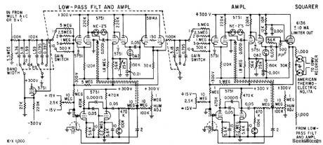
Designed to study dynamic data recorded as frequency-modulated signals on magnetic tape. Filter circuit values give 1, 2, and 4-cps bandwidth in analyzer. Thermocouple in squarer has time constant of 1 sec so output is filtered as well as squared. Outputs of thermocouples are in series to provide summing. D-c amplifiers prevent loading of filters,-T. B. Fryer, Frequency Analyzer Uses Two Reference signals, Electronics, 32:18, p 56-57. (View)
View full Circuit Diagram | Comments | Reading(809)
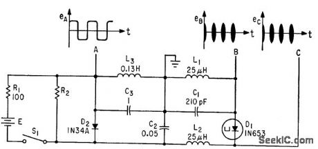
SQUARE_WAVES_FROM_MVBR
Published:2009/7/24 2:12:00 Author:Jessie
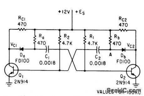
Use of four additional components (two resistors and two diodes) with basic free-running mvbr changes its output to dean square wave. Operating range is from several cps to several Mc.-R. O. Gregory and J. C. Bowers, Simple Square-Wave Generator, Electronics, 35:51, p 47. (View)
View full Circuit Diagram | Comments | Reading(617)
FM_IF_PLI_detector_double_conversion_and_RF_mixer
Published:2009/7/24 2:12:00 Author:Jessie
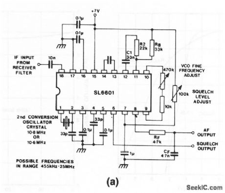
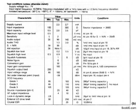
The SL6601 used in this circuit is a straight-through or single-conversion IF amplifier and detector for FM-radio applications. Figure 2-10B shows the electrical characteristics. A typical value for timing capacitor C is 390 pF. (View)
View full Circuit Diagram | Comments | Reading(1216)
COHO
Published:2009/7/24 2:12:00 Author:Jessie
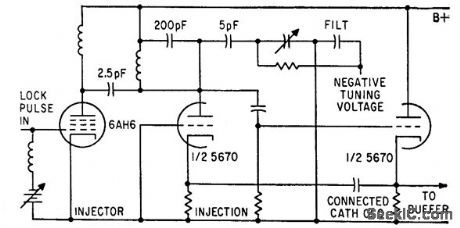
Connected-cathode coherent oscillator has compromise between good short-term frequency stability and good locking ability, as required for measuring pulse-to-pulse phase variation in pulsed r-f systems.-R. H. Holman and R. B. Shields, Measuring Frequency Stability of Pulsed Signals, Electronics, 34:16, p 61-65. (View)
View full Circuit Diagram | Comments | Reading(726)
QUADRATURE__OSCILLATOR
Published:2009/7/2 7:45:00 Author:May

Addition of diode limiter and positive-feedback resistor to UAF41 universal active filtrer gives precision quadrature oseillator.-Y. J. Wong, Design a Low Cost, Low-Distortion, Precision Sine-Wave Oscillator,EDN Magazzine,Sept20, 1978,p 107-113. (View)
View full Circuit Diagram | Comments | Reading(939)
MODULATOR_WITH_FEEDBACK
Published:2009/7/24 2:11:00 Author:Jessie
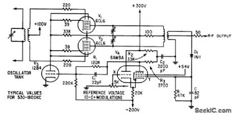
Automatic amplitude stabilization of r-f test signals, within 1 db over 1,300 to 1 frequency range, is achieved by demodulating r-f output with D1 and feeding demodulated voltage back to grid Y of differential amplifier V4. Permits rapid and accurate response measurements over wide range without resetting signal level to input of device under lest.-A. Fong, Feedback Stabilizes Signal Generator, Electronics, 33:29, p 71-73. (View)
View full Circuit Diagram | Comments | Reading(537)
LINEAR_FREQUENCY_SWEEP_GENERATOR
Published:2009/7/24 2:10:00 Author:Jessie

Frequency is swept from 400 to 600 kc electronically by using reverse-biased pn junction diode C as variable capacitor in oscillator V5. Frequency markers are provided. Output is amplified and filtered to give 6 w into 150 ohms with high purity of wave form.-M. M. Brady, Oscillator Design Using Voltage-Variable Capacitors, Electronics, 32:34, p 38-40. (View)
View full Circuit Diagram | Comments | Reading(1301)
| Pages:119/195 At 20101102103104105106107108109110111112113114115116117118119120Under 20 |
Circuit Categories
power supply circuit
Amplifier Circuit
Basic Circuit
LED and Light Circuit
Sensor Circuit
Signal Processing
Electrical Equipment Circuit
Control Circuit
Remote Control Circuit
A/D-D/A Converter Circuit
Audio Circuit
Measuring and Test Circuit
Communication Circuit
Computer-Related Circuit
555 Circuit
Automotive Circuit
Repairing Circuit