
Oscillator Circuit
Index 43
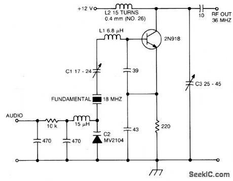
CRYSTAL_OSCILLATOR_DOUBLER
Published:2009/6/24 23:30:00 Author:May

Circuit Notes
The crystal operates into a complex load at series resonance. L1, C1, and C2 balance the crystal at zero reactance. Capacitor C1 fine-tunes the center frequency. Tank circuit L2, C3 doubles the output frequency the circuit operates as an FM oscillator-doubler. (View)
View full Circuit Diagram | Comments | Reading(841)
OVERTONE_OSCILLATOR_WITH_CRYSTAL_SWITCHING
Published:2009/6/24 23:18:00 Author:May

Circuit Notes
The large inductive phase shift of L1 is compensated for by C1. Overtone crystals have very narrow bandwidth; therefore, the trimmer has a smaller effect than for fundamental-mode operation. (View)
View full Circuit Diagram | Comments | Reading(0)
CRYSTAL_CONTROLLED_BUTLER_OSCILLATOR
Published:2009/6/24 23:13:00 Author:May

Circuit NotcsA typical Butler oscillator (20-100 MHz) uses an FET in the second stage; the circuit is not reliable with two bipolars. Sometimes two FETs are used. Frequency is determined by LC values. (View)
View full Circuit Diagram | Comments | Reading(0)
FIFTH_OVERTONE_OSCILLATOR
Published:2009/6/24 23:06:00 Author:May

Circuit NotesThis circuit isolates the crystal from the dc base supply with an rf choke for better starting characteristics. (View)
View full Circuit Diagram | Comments | Reading(0)
50_MHz_150_MHz_OVERTONE_OSCILLATOR
Published:2009/6/24 23:02:00 Author:May

View full Circuit Diagram | Comments | Reading(0)
SCHMITT_TRIGGER_CSCILLATOR
Published:2009/6/24 22:57:00 Author:May
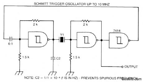
Circuit NotesA Schmitt trigger provides good squaring of the output, sometimes eliminating the need for an extra output stage. (View)
View full Circuit Diagram | Comments | Reading(775)
VOLTAGE_CONTROLLED_TWO_PHASE_OSCILLATOR
Published:2009/6/24 22:00:00 Author:May
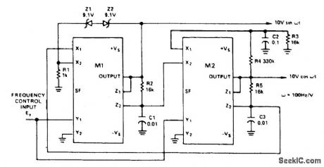
This circuit uses two multipliers for integration-with-contro llable-time -constants in a feedback loop. R2 and R5 will be recognized in the AD534 voltage-to-current configuration; the currents are integrated in C1 and C3, and the voltages they develop are connected at high impedance in proper polarity to the X inputs of the next AD534. The frequency-control input, EY, varies the integrator gains, with a sensitivity of 100 Hz/V, and frequency error typically less than 0.1% of full scale from 0.1V to 10V (10 Hz to 1 kHz). C2 (proportional to C1 and C3), R3, R4 provide regenerative darnp-ing to start and maintain oscillation. Z1 and Z2 stabilize the amplitude at low distortion by degenera-tive damping above ±10V. (View)
View full Circuit Diagram | Comments | Reading(582)
THREE_DECADE_VCO
Published:2009/6/24 21:59:00 Author:May
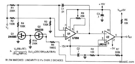
A range of 10 Hz to 10 kHz is covered by this circuit. (View)
View full Circuit Diagram | Comments | Reading(665)
4093_CMOS_VFO
Published:2009/6/24 21:52:00 Author:May

Two gates of a Quad 4093 are used in an astable multivibrator. C1 is a three-gang 365 pF variable capacitor with sections paralleled. S3 and S4 switch in optional extra capacitors. (View)
View full Circuit Diagram | Comments | Reading(2663)
SIMPLE_AUDIO_TEST_OSCILLATOR
Published:2009/6/24 21:50:00 Author:May

An 88-mH surplus telephone toroidal coil is used in a 1-kHz oscillator. Up to 8 V p-p into a high-Z load is available. THD is 0.9%. (View)
View full Circuit Diagram | Comments | Reading(1116)
4093_CMOS_ASTABLE_OSCILLATOR
Published:2009/6/24 21:48:00 Author:May

Two gates of the Quad 4093 are used to make an oscillator. RX can be from about 5 kΩ to around 10 MΩ. CX can be from about 10 pF to many μF, the limit being set by the leakage of the capacitor. Frequency is approximately 2.8/RXCX (R MΩ, Cmfd). (View)
View full Circuit Diagram | Comments | Reading(3793)
VARIABLE_DUTY_CYCLE_OSCILLATOR
Published:2009/6/24 21:42:00 Author:May

Using a potentiometer and steering diodes, this 1.2-kHz oscillator will provide 1 to 99% duty cycle. Vary C1 to change frequency. (View)
View full Circuit Diagram | Comments | Reading(0)
WIEN_BRIDGE_AUDIO_OSCILLATOR
Published:2009/6/24 21:39:00 Author:May
For variable-frequency operation, R1 and R2 can be replaced by a dual potentiometer. (View)
View full Circuit Diagram | Comments | Reading(604)
PRECISION_GATED_OSCILLATOR
Published:2009/6/24 21:37:00 Author:May
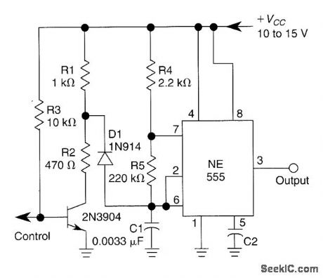
A 1-kHz gated oscillator with no long turn-on cycle is shown. R2, R3, and D1 preset the voltage on tuning capacitor C1 to 1/3 of the supply voltage. (View)
View full Circuit Diagram | Comments | Reading(725)
CMOS_VFO
Published:2009/6/24 21:31:00 Author:May

The circuit shown has a frequency range of 2 Hz to 30 kHz. R2 is a linear or log potentiometer. (View)
View full Circuit Diagram | Comments | Reading(0)
CRYSTAL_OSCILLATOR
Published:2009/6/24 21:28:00 Author:May

Circuit NotesStable VXO using 6-or 8-MHz crystals uses a capacitor and an inductor to achieve frequency pulling on either side of series resonance. (View)
View full Circuit Diagram | Comments | Reading(0)
SIMPLE_TTL_CRYSTAL_OSCILLATOR
Published:2009/6/24 21:25:00 Author:May

Circuit NotesThis simple and cheap crystal oscillator comprises one third of a 7404, four resistors and a crystal. The inverters are biased into their linear regions by RI to R4, and the crystal provides the feedback. Oscillation can only occur at the crystals fundamental frequency. (View)
View full Circuit Diagram | Comments | Reading(10041)
VARIABLE_WIEN_BRIDGE_OSCILLATOR
Published:2009/6/24 21:15:00 Author:May

This circuit uses a single potentiometer to tune a 300- to 3000-Hz range. A FET op amp is used at A1 and A2. The upper frequency limit is determined by the gain-bandwidth product of the op amps. (View)
View full Circuit Diagram | Comments | Reading(0)
BASIC_OSCILLATOR_CIRCUITS
Published:2009/6/24 21:12:00 Author:May


Five basic types of LC oscillators are shown. The frequency can be changed by using the formula:where Leffective =equivalent inductance Ceffective =equivalent capacitance (View)
View full Circuit Diagram | Comments | Reading(0)
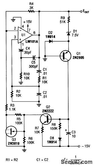
PRECISION_LF_OSCILLATOR
Published:2009/6/24 21:07:00 Author:May

Using R1, R7, and D1 to preset C1 to one third of the supply voltage, this circuit avoids a longer first cycle period than subsequent cycles. (View)
View full Circuit Diagram | Comments | Reading(0)
| Pages:43/54 At 204142434445464748495051525354 |
Circuit Categories
power supply circuit
Amplifier Circuit
Basic Circuit
LED and Light Circuit
Sensor Circuit
Signal Processing
Electrical Equipment Circuit
Control Circuit
Remote Control Circuit
A/D-D/A Converter Circuit
Audio Circuit
Measuring and Test Circuit
Communication Circuit
Computer-Related Circuit
555 Circuit
Automotive Circuit
Repairing Circuit