Oscillator Circuit
VOLTAGE_CONTROLLED_TWO_PHASE_OSCILLATOR
Published:2009/6/24 22:00:00 Author:May | From:SeekIC
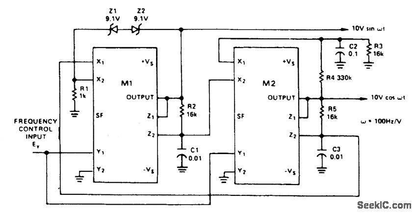
This circuit uses two multipliers for integration-with-contro llable-time -constants in a feedback loop. R2 and R5 will be recognized in the AD534 voltage-to-current configuration; the currents are integrated in C1 and C3, and the voltages they develop are connected at high impedance in proper polarity to the X inputs of the next AD534. The frequency-control input, EY, varies the integrator gains, with a sensitivity of 100 Hz/V, and frequency error typically less than 0.1% of full scale from 0.1V to 10V (10 Hz to 1 kHz). C2 (proportional to C1 and C3), R3, R4 provide regenerative darnp-ing to start and maintain oscillation. Z1 and Z2 stabilize the amplitude at low distortion by degenera-tive damping above ±10V.
Reprinted Url Of This Article:
http://www.seekic.com/circuit_diagram/Signal_Processing/Oscillator_Circuit/VOLTAGE_CONTROLLED_TWO_PHASE_OSCILLATOR.html
Print this Page | Comments | Reading(3)

Article Categories
power supply circuit
Amplifier Circuit
Basic Circuit
LED and Light Circuit
Sensor Circuit
Signal Processing
Electrical Equipment Circuit
Control Circuit
Remote Control Circuit
A/D-D/A Converter Circuit
Audio Circuit
Measuring and Test Circuit
Communication Circuit
Computer-Related Circuit
555 Circuit
Automotive Circuit
Repairing Circuit
Code: