
Oscillator Circuit
Index 42
STABLE_LOWFREQUENCY_CRYSTAL_OSCILLATOR
Published:2009/6/25 3:02:00 Author:May
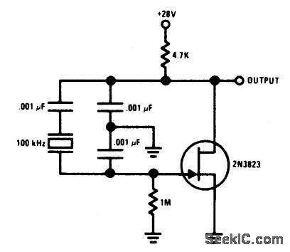
Circuit Notes This Colpitts-crystal oscillator IS ideal forlow frequency crystal oscillator circuits。 Ex-cellent stability is assured because the 2N3823 JFET circuit loading does not vary with tem-perature. (View)
View full Circuit Diagram | Comments | Reading(1073)
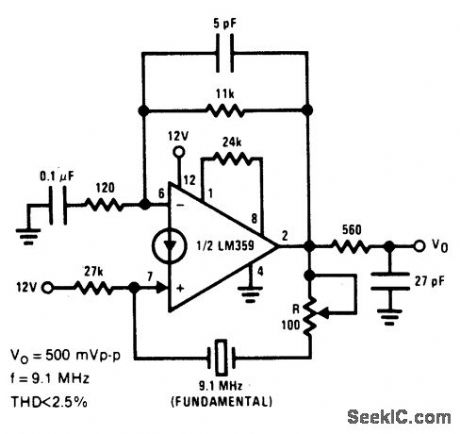
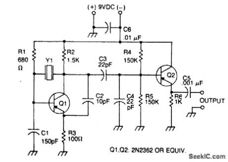
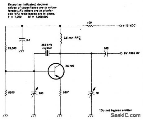
CRYSTAL_CONTROLLED___SINE_WAVE_OSCILLATOR_
Published:2009/6/25 3:00:00 Author:May
View full Circuit Diagram | Comments | Reading(791)
TTL_COMPATIBLE_CRYSTAL_OSCILLATOR
Published:2009/6/25 2:57:00 Author:May

Circuit NotesAdjust RI for about 2 volts at the output ofthe first gate,Adjust C1 for best output (View)
View full Circuit Diagram | Comments | Reading(762)
STANDARD_CRYSTALOSCILLATOR_FOR_1_MHz
Published:2009/6/25 2:55:00 Author:May

View full Circuit Diagram | Comments | Reading(583)
INTERNATIONAL_CRYSTAL_OF_1_HI_OSCILLATOR
Published:2009/6/25 2:55:00 Author:May
Circuit NotesInternational Crystal OF-1 HI oscillator circuit for third-overtone crystals. The circuit does not requlre inductors. (View)
View full Circuit Diagram | Comments | Reading(717)
BUTLER_APERIODIC_OSCILLATOR
Published:2009/6/25 2:50:00 Author:May
Circuit Notes
This circuit works well in the range of 50 kHz to 500 kHz. Slight component modifica-tions are needed for higher frequency opera-tion. For operation over 3000 kHz, select a transistor that provides moderate gain (in the 60 to 150 range) at the frequency of operation and a gain-bandwidth product of at least 100 MHz. (View)
View full Circuit Diagram | Comments | Reading(628)
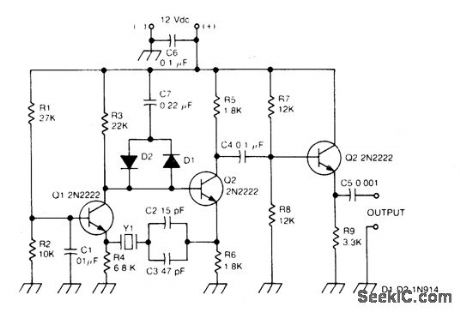
PIERCE_OSCILLATOR
Published:2009/6/25 2:36:00 Author:May
Circuit Notes
The oscillator transistor is Q1, and the crystal is placed between the collector and base. Feedback is improved by the use of the collector-emitter capacitor C2. Transistor Q2 is used as an output buffer. (View)
View full Circuit Diagram | Comments | Reading(0)
CRYSTAL_CONTROLLED_OSCILLATOR
Published:2009/6/25 2:35:00 Author:May


Circuit Notes
This circuit oscillates without the crystal. With the crystal in the circuit, the frequency will be that of the crystal. The circuit has good starting characteristics even with the poorest crystals. (View)
View full Circuit Diagram | Comments | Reading(0)
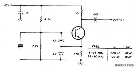
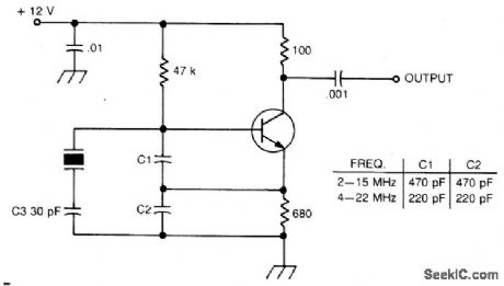
COLPITTS_OSCILLATOR
Published:2009/6/25 2:32:00 Author:May

Circuit Notes
This circuit will operate with fundamental-mode crystals in the range of 1MHz to 20 MHz,Feedback is controlled by capacitor voltage divider C2/C3.The rfvoltageacross the emitter resistor provides the basic feedback signal. (View)
View full Circuit Diagram | Comments | Reading(0)
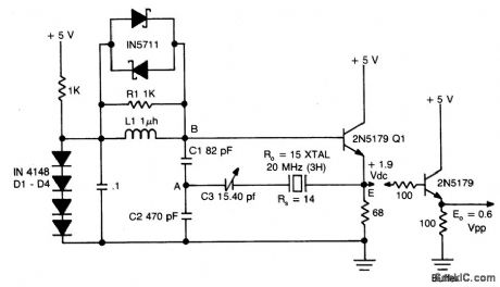
BUTLER_EMITTER_FOLLOWER_OSCILLATOR(20_MHz)
Published:2009/6/25 2:26:00 Author:May
View full Circuit Diagram | Comments | Reading(0)
TUBE_TYPE_CRYSTAL_OSCILLATOR
Published:2009/6/25 2:20:00 Author:May

Circuit Notes
The pilot lamp limits current to prevent damage to the crystal. (View)
View full Circuit Diagram | Comments | Reading(834)
PIERCE_HARMONIC_OSCILLATOR(BASIC_CIRCUIT)
Published:2009/6/25 2:20:00 Author:May

Circuit Notes
This circuit operates 10-40 ppm above series resonance. It is a good circuit design with good to very good frequency stability. (View)
View full Circuit Diagram | Comments | Reading(954)
BUTLER_COMMON_BASE_OSCILLATOR_BASIC_CIRCUIT
Published:2009/6/25 2:17:00 Author:May

Circuit Notes This circuit operates at or near series resonance. It has fair to poor circuit design with parasitics, touch to tune, and fair frequency stability. (View)
View full Circuit Diagram | Comments | Reading(0)
COLPITTS_HARMONIC_OSCILLATOR(BASIC_CIRCUIT)
Published:2009/6/25 2:14:00 Author:May

Circuit NotesThis circuit operates 30-200 ppm above series resonance. Physically simple, but analytically complex. It is inexpensive with fair frequency stability. (View)
View full Circuit Diagram | Comments | Reading(0)
INTERNATIONAL_CRYSTAL_OF_1_LO_OSCILLATOR
Published:2009/6/25 2:04:00 Author:May
Circuit Notes
International Crystal OF-1 LO oscillator circuit for fundamental-mode crystals. (View)
View full Circuit Diagram | Comments | Reading(673)
COLPITTS_HARMONIC_OSCILLATOR(100_MHz)
Published:2009/6/25 2:03:00 Author:May
Circuit Notes
L1C1 are selected to be resonant at a frequency below the desired crystal harmonic but above the crystal's next lower odd har-monic. C2 should have a value of 30-70 pF, independent of the oscillation frequency.There is no requirement for any specific ratio of C1/C2, but practical harmonic circuits seem to work best when C1 is approximately 1-3 times the value of C2. Diodes Dl-D3 provide a simple regulated bias supply. The resistance of RI should be as high as possible, as it affects the crystal's in-circuit Q. (View)
View full Circuit Diagram | Comments | Reading(889)
TEMPERATURE_COMPENSATED_CRYSTAL_OSCILLATOR
Published:2009/6/25 1:51:00 Author:May

Circuit NotesTwo different negative-coefficient capacitors change in capacitance to counteract or compensate are blended to produce the desired for the decrease in frequency of the normal AT-cut characteristics. (View)
View full Circuit Diagram | Comments | Reading(0)
CMOS_CRYSTAL_OSCILLATOR
Published:2009/6/25 1:47:00 Author:May


Circuit Notes
This circuit has a frequency range of 0.5 MHz to 2.0 MHz. Frequency can be adjusted to a precise value with trimmer capacitor C2. The second NOR gate serves as an output buffer. (View)
View full Circuit Diagram | Comments | Reading(2169)
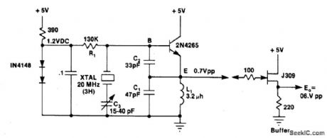
THIRD_OVERTONE_CRYSTAL_OSCILLATOR
Published:2009/6/25 1:42:00 Author:May

Circuit NotesThis circuit uses a 74500 Schottky TTL gate; no inductors are required. (View)
View full Circuit Diagram | Comments | Reading(1013)
LOW_FREQUENCY_CRYSTAL_OSCILLATOR
Published:2009/6/24 23:31:00 Author:May
Circuit NotesThis crystal-oscillator circuit uses crystal. (View)
View full Circuit Diagram | Comments | Reading(0)
| Pages:42/54 At 204142434445464748495051525354 |
Circuit Categories
power supply circuit
Amplifier Circuit
Basic Circuit
LED and Light Circuit
Sensor Circuit
Signal Processing
Electrical Equipment Circuit
Control Circuit
Remote Control Circuit
A/D-D/A Converter Circuit
Audio Circuit
Measuring and Test Circuit
Communication Circuit
Computer-Related Circuit
555 Circuit
Automotive Circuit
Repairing Circuit