
Oscillator Circuit
Index 52
The multivibrator circuit with variable pitch
Published:2011/4/18 0:40:00 Author:Ecco | Keyword: multivibrator , variable pitch
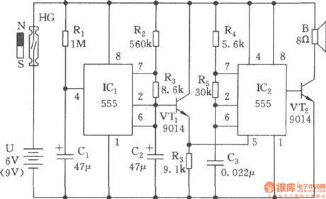
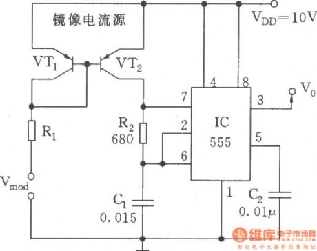
The multivibrator circuit with variable pitch is composed of two 555 time base circuits, it can issue wave of oscillation changed in 400~2500Hz, and its sound is similar to the sound of the public security police. The circuit consists of power-delay, low-frequency oscillator and the modulation generator.
(View)
View full Circuit Diagram | Comments | Reading(747)
Linear vco(8038、μA741)
Published:2011/4/14 22:46:00 Author:Ecco | Keyword: Linear , vco
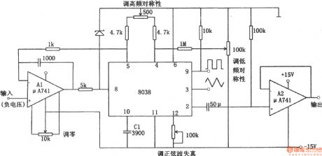
The linear voltage-controlled oscillator circuit is shown as the chart. In the figure, A1 is a constant current source circuit which is used to improve charging and discharging characteristics of C1. It makes a linear relationship between the output frequency and the input control voltage. A2 is a sine wave output buffer. If inputting the low-frequency sawtooth to the control voltage terminal, the circuit will become a linear sweep generator. But putting a signal voltage on input terminal will make the circuit output frequency modulation wave. The circuit can be used as an A / D converter changing a digital signal into the voltage with a frequency counter counting the output. Linear VCO is also known as V / F converter. (View)
View full Circuit Diagram | Comments | Reading(3773)
RF driver audio oscillator
Published:2011/4/14 3:24:00 Author:Ecco | Keyword: RF driver, audio oscillator
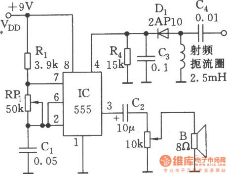
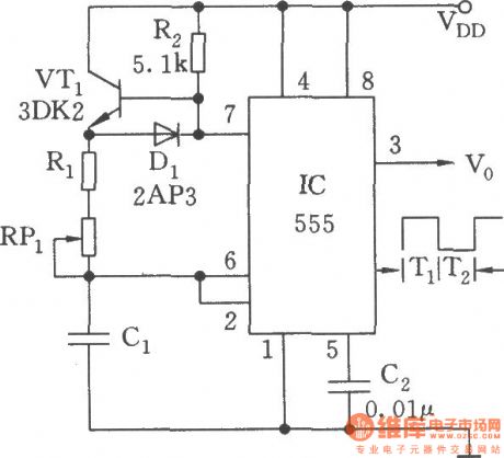
As shown, 555 and Rl, RPl, C1 and other components form controllable audio oscillator, f = 1.44 / (R1 +2 RP1) C1, the frequency of parameter in the diagram is between 600Hz ~ 20kHz, it can be adjustedby RP1.
(View)
View full Circuit Diagram | Comments | Reading(646)
Data-controlled variable frequency oscillator
Published:2011/4/14 3:25:00 Author:Ecco | Keyword: Data-controlled, variable frequency , oscillator
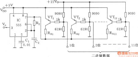
As shown, toaccess 11-bit binary data(highlevel is 1 , low level is 0 )on the base bias circuit of VT1~VT11, there are 2048 combinations. When one pointis in low level, the corresponding VT tube is conducted, the C2 charges through the RA + R2. RAis the equivalent resistance of the resistor connecting to each conducting tube.
(View)
View full Circuit Diagram | Comments | Reading(585)
Multivibrator with symmetric wave output
Published:2011/4/14 3:40:00 Author:Ecco | Keyword: Symmetric wave , output, multivibrator
The chart is as shown. Comparing with the general multivibrator, it adds a biased transistor VT1 to the charging circuit. VT1 can be fully conducted in the effect of R2; When C1 discharges, it will be completely closed. As the forward resistance is low(less than hundreds ohm) when VT1 switch and germanium diode arein the conducting state, it has little influence on charging and discharging time.
Another advantage of this circuit is thatthe loading change has a minimal impact on the output voltage amplitude, duty cycle and oscillation frequency. (View)
View full Circuit Diagram | Comments | Reading(583)
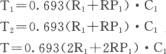
The controlled oscillator composed of Nand gate
Published:2011/4/7 3:32:00 Author:Ecco | Keyword: controlled oscillator, NOT gate
View full Circuit Diagram | Comments | Reading(543)
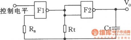
LC oscillator composed of NAND gate
Published:2011/4/7 3:32:00 Author:Ecco | Keyword: LC oscillator , NAND gate
View full Circuit Diagram | Comments | Reading(1489)
Wien oscillator regulator
Published:2011/4/14 2:52:00 Author:Ecco | Keyword: wien , oscillator , regulator
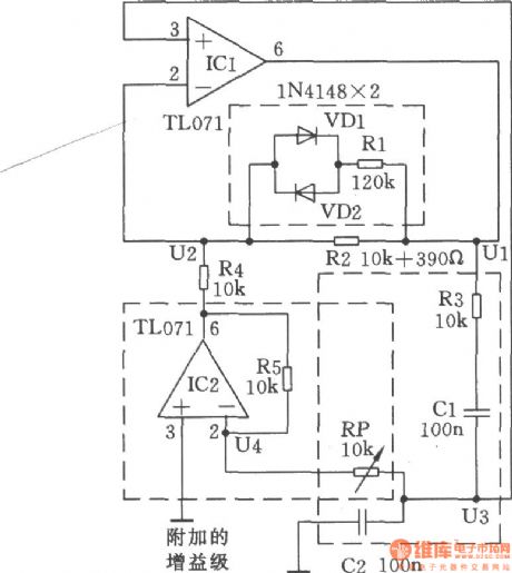
In the Wien bridge, to change any resistance will change the frequency and attenuation. As shown, by adjusting the resistance can change the gain of the amplifier and compensate for the attenuation.
(View)
View full Circuit Diagram | Comments | Reading(526)
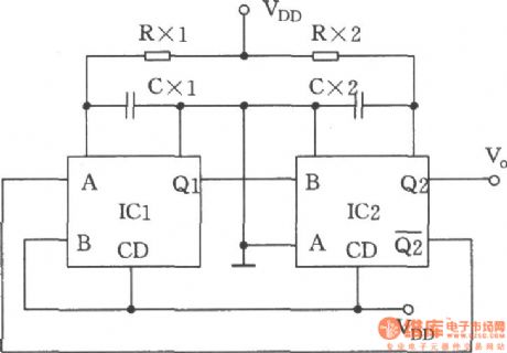
The separate excitation crossover multivibrator
Published:2011/4/14 2:39:00 Author:Ecco | Keyword: separate excitation, crossover, multivibrator

The separate excitation crossover multivibrator is shown in the chart. It has two or four types of split-phase output waveform, and can easily obtain 0°,-90°,-180°, 270°split-phase square wave. It has the features of simple structure, good output waveform, eliminating the traditional frequency, counting, decoding circuit. It should be used in the phase generator, four-cycle water lantern controller circuit,etc.
(View)
View full Circuit Diagram | Comments | Reading(610)
The separate excitation crossover oscillator used in four recirculating water lantern controller
Published:2011/4/14 2:40:00 Author:Ecco | Keyword: separate excitation rossover oscillator, four recirculating , water lantern , controller
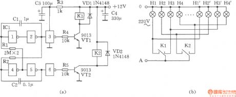
The figure shows the separate excitation crossover oscillator used in four recirculating water lantern controller, the circuit only adopts two sets of contactrelay 4088 to control the four water lanterns. The working principle: the six NOT gate CD4069 in ICl and C1, C2, Rl, R2 form the separate excitation crossover oscillator circuit, it controls the transistor VTl, VT2 directly and drives relays Kl, K2 for the cross-phase output, that is the after Kl pulls, then K2 pulls, and Kl disconnects, K2 then disconnects and go in the cycle. (B) shows the lantern connection diagram.
(View)
View full Circuit Diagram | Comments | Reading(536)
NC monostable multivibrator circuit
Published:2011/4/14 2:40:00 Author:Ecco | Keyword: NC, monostable , multivibrator

The NC monostable multivibrator circuit shown in the chart is composed of four 2 input NOR gate CC4001 and 14-bit binary serial counter / divider CC4020. It mainly used as time delay switch or timer in automatic control equipments. (View)
View full Circuit Diagram | Comments | Reading(1726)
Variable duty cycle monostable multivibrator composed of 74HCT221
Published:2011/4/13 3:17:00 Author:Ecco | Keyword: Variable duty cycle, monostable multivibrator
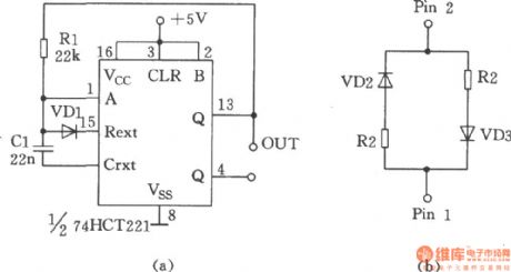
The chart shows the variable duty cycle monostable multivibrator composed of 74HCT221. Capacitor C is charged and discharged at the same rate, the duty cycle is 50%, the oscillation period T = RC. The R in figure (a) can be replaced by the map to get other desired duty cycle, during this time, Cl is charged by R1, and discharged by R2, the oscillation period T = (R1 + R2) C / 2, the duty cycle is approximately Rl / (R1 + R2). In the figure 9-11, VDl, VD2, VD3 is the 1N4148. (View)
View full Circuit Diagram | Comments | Reading(1150)
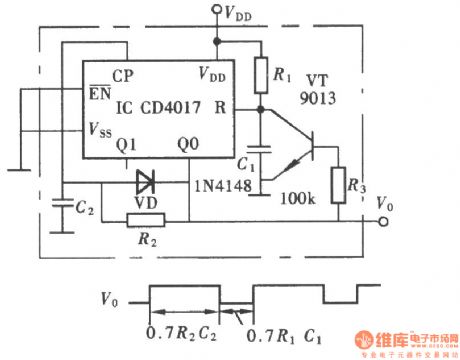
The multivibrator composed of CD4017
Published:2011/4/13 2:17:00 Author:Ecco | Keyword: multivibrator
View full Circuit Diagram | Comments | Reading(613)
Rapid synchronous vco
Published:2011/4/12 22:52:00 Author:Ecco | Keyword: Rapid , synchronous, vco
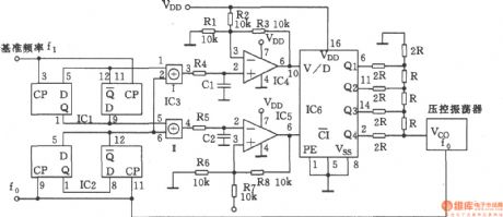
The main function of this circuit is to combine phase splitter and digital / analog converter, it can make the high stability VCO and the external reference frequency be precisely synchronized. (View)
View full Circuit Diagram | Comments | Reading(617)
Special sound audio oscillator circuit(NE555、CD4017)
Published:2011/4/6 20:12:00 Author:Ecco | Keyword: Special sound , audio oscillator

View full Circuit Diagram | Comments | Reading(3109)
Linear voltage-controlled oscillator(555)
Published:2011/4/10 22:13:00 Author:Ecco | Keyword: Linear , voltage-controlled oscillator, 555
View full Circuit Diagram | Comments | Reading(942)
Negative resistance LED oscillation circuit
Published:2011/4/10 22:38:00 Author:Nicole | Keyword: negative resistance, LED, oscillation
This circuit can cover 3.2~8.0 kHz frequency range. It can inspire the loudspeaker which is connected on X point. In oder to obtain lower frequency and large sound, it should change C1 into 1μF. The negative resistance part of this circuit consists of Q1, Q2, LED, R2 and R3. Optical isolator device is MCF-2 or equivalent component. (View)
View full Circuit Diagram | Comments | Reading(618)
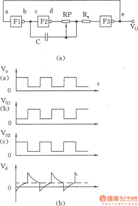
The ring oscillator with delay circuit composed of TTL NOT gate
Published:2011/4/6 4:08:00 Author:Ecco | Keyword: ring oscillator , delay circuit , TTL NOT gate
View full Circuit Diagram | Comments | Reading(1249)
Duty ratio and frequency adjustable multivibrator composed of double monostable trigger CC4528
Published:2011/4/6 20:11:00 Author:Ecco | Keyword: Duty ratio , frequency adjustable , multivibrator, double monostable trigger
View full Circuit Diagram | Comments | Reading(580)
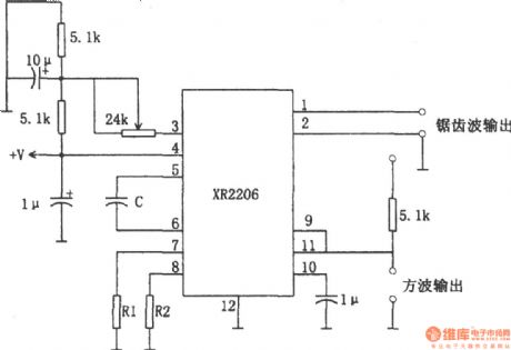
Square wave and sawtooth wave oscillator composed of XR2206
Published:2011/4/6 2:42:00 Author:Ecco | Keyword: Square wave , sawtooth wave , oscillator
View full Circuit Diagram | Comments | Reading(2238)
| Pages:52/54 At 204142434445464748495051525354 |
Circuit Categories
power supply circuit
Amplifier Circuit
Basic Circuit
LED and Light Circuit
Sensor Circuit
Signal Processing
Electrical Equipment Circuit
Control Circuit
Remote Control Circuit
A/D-D/A Converter Circuit
Audio Circuit
Measuring and Test Circuit
Communication Circuit
Computer-Related Circuit
555 Circuit
Automotive Circuit
Repairing Circuit