Oscillator Circuit
Linear vco(8038、μA741)
Published:2011/4/14 22:46:00 Author:Ecco | Keyword: Linear , vco | From:SeekIC

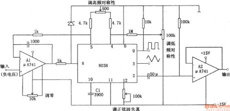
The linear voltage-controlled oscillator circuit is shown as the chart. In the figure, A1 is a constant current source circuit which is used to improve charging and discharging characteristics of C1. It makes a linear relationship between the output frequency and the input control voltage. A2 is a sine wave output buffer. If inputting the low-frequency sawtooth to the control voltage terminal, the circuit will become a linear sweep generator. But putting a signal voltage on input terminal will make the circuit output frequency modulation wave. The circuit can be used as an A / D converter changing a digital signal into the voltage with a frequency counter counting the output. Linear VCO is also known as V / F converter.
Reprinted Url Of This Article:
http://www.seekic.com/circuit_diagram/Signal_Processing/Oscillator_Circuit/Linear_vco8038-μA741.html
Print this Page | Comments | Reading(3)

Article Categories
power supply circuit
Amplifier Circuit
Basic Circuit
LED and Light Circuit
Sensor Circuit
Signal Processing
Electrical Equipment Circuit
Control Circuit
Remote Control Circuit
A/D-D/A Converter Circuit
Audio Circuit
Measuring and Test Circuit
Communication Circuit
Computer-Related Circuit
555 Circuit
Automotive Circuit
Repairing Circuit
Code: