
Amplifier Circuit
Index 82
FEEDBACK_AMPLIFIER_INTEGRATOR
Published:2009/7/16 22:38:00 Author:Jessie
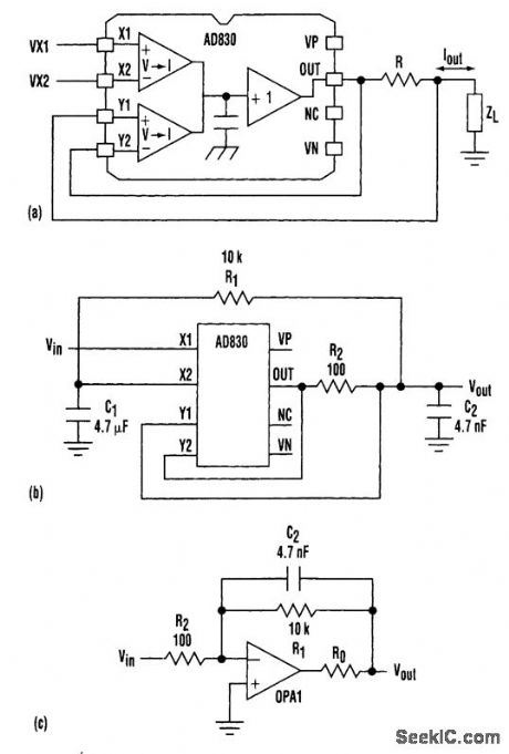
The active-feedback-amplifier topology, such as that in the AD830 from Analog Devices and Lin-ear Technology's LTC1193, can be used to produce a precision voltage-to-current converter. This, in turn, makes possible the creation of grounded-capacitor integrators. This circuit can be used as a differential input integrator by making ZL a capacitor. Figure 1b and 1c compares the grounded-capacitor integrator using the AD830 with a standard op-amp integrator. R1 in both figures and C1 in Fig.16 define the dc operating point for testing purposes. R2 and C2 determine the integrator time constant. If the op amp in Fig.1c is ideal in the sense that it is modeled as an ideal integrator with zero output and infinite input resistance, then the only difference between the two circuit topologies is the finite input resistance of the op-amp circuit determined by R2.
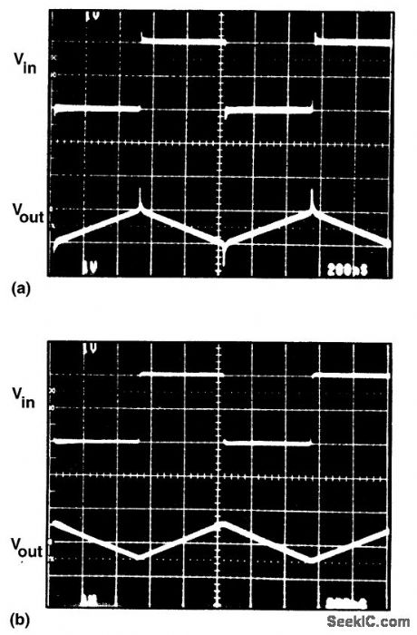
A large spike is produced on the output voltage waveform whenever the input switches using the circuit with the standard op-amp integrator (a). The integrator using the AD830 has no spike in its output waveform because the capacitor is connected to a true ground (b). (View)
View full Circuit Diagram | Comments | Reading(1402)
FAST_AMPLIFIER_FOR_RANDOM_TELEGRAPH_WAVE
Published:2009/7/16 22:34:00 Author:Jessie
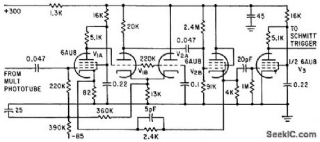
Amplifies small pulses above thresh-old value without being overloaded by large pulses derived from radioactive isotope and phosphor on envelope of multiplier photo-tube. Two feedback loops, similar to Oak Ridge-Fairstein and Brookhaven-Chase circuits, help to stabilize gain.-J. B. Manelis, Generating Random Noise with Radioactive Sources, Electronics, 34:36, p 66-69. (View)
View full Circuit Diagram | Comments | Reading(585)
HF_AMPLIFIER_GROUNDING_TECHNIQUE
Published:2009/7/16 22:32:00 Author:Jessie
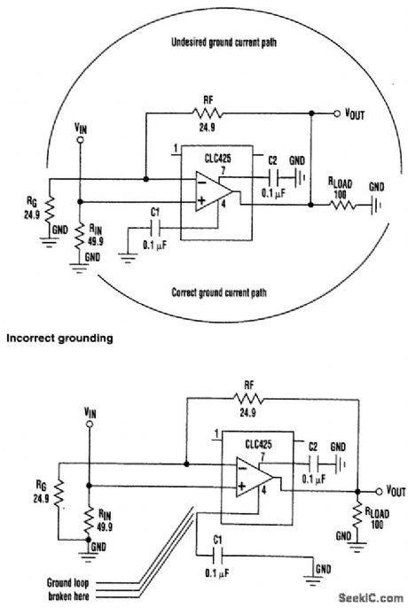
Incorrect grounding on a high-frequency amplifier allows the addition of polarized signal back into the input. Improved grounding is provided by common grounds at the input, physical orientation of a bypass capacitor, and breaking a ground loop. (View)
View full Circuit Diagram | Comments | Reading(691)
MAGNETICALLY_REGULATED_D_C_SUPPLY
Published:2009/7/17 1:24:00 Author:Jessie

Magamps and saturating transformer maintain output regulation,within 3% for variation up to 20 V in supply voltage.Sillcon rectifiers in bridges convert a-c supply to d-c output at five different levels. Article gives all transformer winding data.-M. B. Meunier,Magnetic Amplifiers Regulate D-C Supply, Electronics, 31:9, p 68-70. (View)
View full Circuit Diagram | Comments | Reading(640)
400_CPS_SERVO_MOTOR_DRIVE
Published:2009/7/17 1:28:00 Author:Jessie

Self-balancing single-stage magnetic amplifier has high response speed, excellent stability, excellent linearity, and freedom from drift. Provides half-cycle response as operational amplifier. Article gives winding data for saturable reactors.-J. Markus, Handbook of Electronic Control Circuits, McGraw. Hill, N.Y,, 1959, p 107. (View)
View full Circuit Diagram | Comments | Reading(665)
MAGAMPS_CONTROL_SCR_BRIDGE
Published:2009/7/17 1:27:00 Author:Jessie

Single-phase bridge is controlled by two half-wave magnetic amplifiers each having a transistor emitter-follower used as clipper for each half-wave voltage output. Used for adjustable d-c field supply.-T. E. DeViney, Semiconductors Improve Reliability of Steel-Mill Control Equipment, Electronics, 34:23, p104-107. (View)
View full Circuit Diagram | Comments | Reading(782)
MODIFIED_ANALOG_MULTIPLIER
Published:2009/7/17 1:25:00 Author:Jessie
Input signal voltages are obtained from center-tapped 2,000-ohm input resistor so that each signal may change its polarity Circuit then Provides unidirectinal output voltage EL which:is equal to square of ES.J, Markus,” Handbook of Electronic Control Circuits,”McGraw-Hill. N.Y,1959,p 103. (View)
View full Circuit Diagram | Comments | Reading(585)
FOUR_QUADRANT_ANALOG_MULTIPLIER
Published:2009/7/17 1:31:00 Author:Jessie
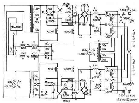
Uses two square-law multiplier circuits con taining only magnetic cores, silicon diodes, and resistors, to provide first square term of algebraic sum of currents I1 and I2, and second square term of difference of these cur rents.-J. Markus, Handbook of Electronic Control Circuits, McGraw-Hill, N.Y. 1959, p 104. (View)
View full Circuit Diagram | Comments | Reading(587)
AMPLIFIER_FOR_10_NSEC_PULSES
Published:2009/7/12 22:06:00 Author:May
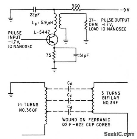
Requires accurately wound pulse transformer in which secondary is close-wound over end of primary that is a-c ground, with accurate control of unsymmetrical distributed capacitance,to serve as building block of 50-megapulse computer. Commercial equivalent of L-5447 is 2N769 or 2N976.-K. H. Konkle and J. E.Laynor, Key to Faster Computers: Ten-Nano-second Amplifier, Electronics, 35:50, p39-41. (View)
View full Circuit Diagram | Comments | Reading(637)
DIFFERENTIAL_MAGNETIC_INVERTER
Published:2009/7/17 1:30:00 Author:Jessie
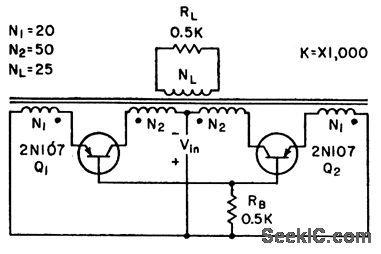
Oscillates reliably without use of current bias. Excessive drive will not cause transistor overheating. Differential action of collector and emitter windings greatly improves performance as compared to conventional nondif-ferential inverter and eliminates need for clipping diodes.-J. Markus, Handbook of Electronic Control Circuits, McGraw-Hill, N.Y., 1959, p 103. (View)
View full Circuit Diagram | Comments | Reading(559)
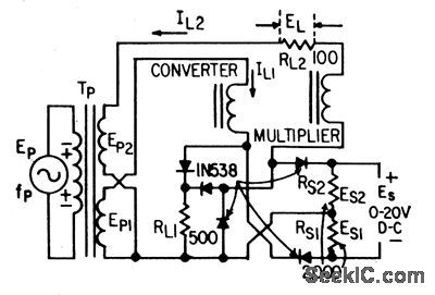
BASIC_ANALOG_MULTIPLIER
Published:2009/7/17 1:44:00 Author:Jessie
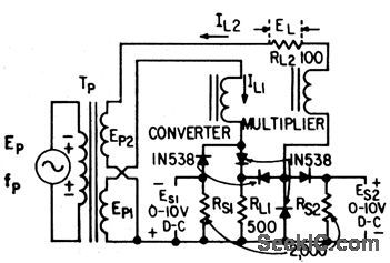
Multiplies d-c voltages ES1 and ES2 in two-stage arrangement in which converter is input stage con trolled by one signal voltage and multiplier is output stage controlled by other signal voltage.-J. Markus, Handbook of Electronic Control Circuits, McGraw-Hill, N.Y., 1959, p 103. (View)
View full Circuit Diagram | Comments | Reading(715)
TWO_SPEED_SERVO_MOTOR_DRIVE
Published:2009/7/17 1:41:00 Author:Jessie
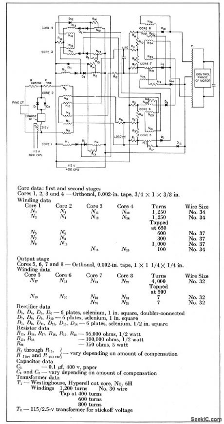
Consists of two conventional half-wave bridge-type stages driving full-wave slave-type output stage. Designed to replete former electron-tube amplifier of two-phase servo system using fine and coarse control transformers.-J. Markus, Handbook of Electronic Control Circuits, McGraw-Hill, N.Y., 1959, p 112. (View)
View full Circuit Diagram | Comments | Reading(632)
VOLTAGE_COMPARATORS
Published:2009/7/12 21:44:00 Author:May
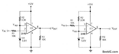
These two comparators are over- and under-voltage comparators. In Fig. 104,5(a), if VIN exceeds the reference voltage, the output of IC1 goes low. In Fig. 104-5(b). if the VIN exceeds the reference, VOUT goes high. (View)
View full Circuit Diagram | Comments | Reading(667)
SENSE_AMPLIFIER_AND_GATE
Published:2009/7/12 21:30:00 Author:May
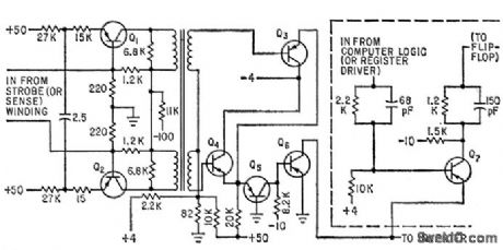
Uses drive-sampling core to generate precisely defined strobe for coincident-current memory.-A.H.Ashley and E.U. Cohler,solving Noise Problems in Digital compuler Memories Electronics,33:13,p72-74. (View)
View full Circuit Diagram | Comments | Reading(460)
THIN_FILM_SENSE_AMPLIFIER
Published:2009/7/12 21:24:00 Author:May
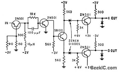
Common-base input stage matches low input impedance of sense winding. 5-mv input signal is boosted to 3-v level. Zener diodes shifl d-c levels of output signal to desired 0 to+3 v level.-E.E. Bittmann, Using Thin Films in High-Speed Memories, Electronics, 32:23, p55-57. (View)
View full Circuit Diagram | Comments | Reading(538)
BUFFER_MEMORY_SENSE_AMPLlFIER
Published:2009/7/12 21:13:00 Author:May
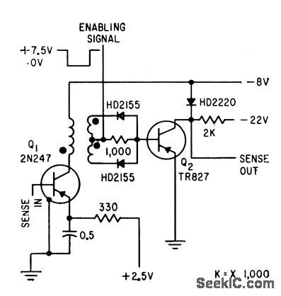
Uses coincident-current technique. Full-wave rectifier is required at secondary of transformer because sense output can be of either polarity. Enabling signal turns on sense amplifier, to permit discrimination between memory core outputs during unload and load cycles.-D.Haagens, Compact Memories Have Flexible Capacities, Electronics, 32:40, p50-53. (View)
View full Circuit Diagram | Comments | Reading(552)
CAPACITOR_ALLOWS_HIGHER_SLEW_RATES
Published:2009/7/12 21:11:00 Author:May
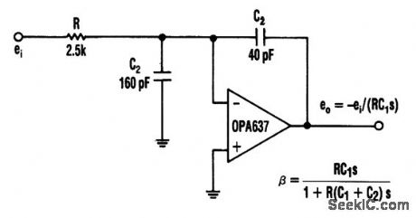
In this circuit, a Burr-Brown op amp supplies a slew rate of 135 V/μs. The addition of C2 charges the high-frequency feedback factor to less than unity, and allows higher slew-rate amplifiers to be compensated for greater-than-unity gain. (View)
View full Circuit Diagram | Comments | Reading(662)
MATRIX_READOUT
Published:2009/7/12 20:54:00 Author:May
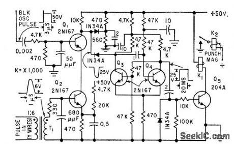
Used for data reduction in telephone traffic data recorder system to permit recording all information on a call as one entry. Coincidence circuit Q1-Q2 provides reliable sensing of matrix output in presence of noise generated by rotary switches and relays.-J. W. Blonchard, E. C. Bellee, and J. Smith, Ferrite Memories Simplify Telephone Data Analysis, Electronics, 32:41, p 68-70. (View)
View full Circuit Diagram | Comments | Reading(517)
VOLTAGE_COMPARATOR
Published:2009/7/12 20:54:00 Author:May
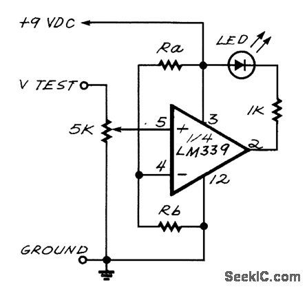
The LED turns on when the input voltage at pin 5 of the LM339 falls below the reference voltage at pin 4. (View)
View full Circuit Diagram | Comments | Reading(0)
FAST_TTL_COMPATIBLE_COMPARATOR
Published:2009/7/12 20:53:00 Author:May
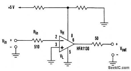
The HFA1130 by Harris Semiconductor is useful as a comparator. Depicted is an inverting 2-ns comparator with TTL-compatible output levels that are realized by using the HFA1130 output-limiting, current-feedback amplifier. (View)
View full Circuit Diagram | Comments | Reading(702)
| Pages:82/250 At 2081828384858687888990919293949596979899100Under 20 |
Circuit Categories
power supply circuit
Amplifier Circuit
Basic Circuit
LED and Light Circuit
Sensor Circuit
Signal Processing
Electrical Equipment Circuit
Control Circuit
Remote Control Circuit
A/D-D/A Converter Circuit
Audio Circuit
Measuring and Test Circuit
Communication Circuit
Computer-Related Circuit
555 Circuit
Automotive Circuit
Repairing Circuit