
Amplifier Circuit
Index 96
Low_noise_flat_frequency_response_preamplifier_using_an_ECG1020_thin_film_hybrid_module
Published:2009/7/20 2:44:00 Author:Jessie
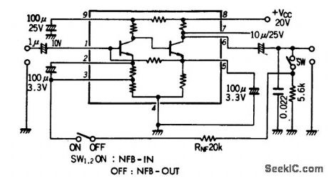
Low-noise flat-frequency-response preamplifier using an ECG1020 thin-film hybrid module. At 1 kHz with the switch off typical voltage gain is 66 dB; with the switch on typical voltage gain is 42.5 dB (courtesy GTE Sylvania Incorporated). (View)
View full Circuit Diagram | Comments | Reading(820)
1_watt_phonograph_amplifier_for_ceramic_cartridges_with_16_ohm_speaker
Published:2009/7/20 2:30:00 Author:Jessie
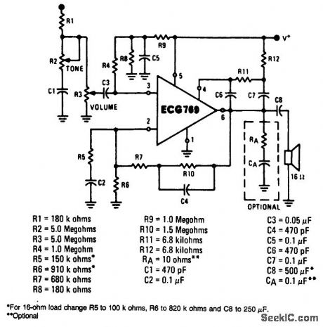
1-watt phonograph amplifier for ceramic cartridges with 16-ohm speaker. See table for component values. Sensitivity is approximately 450 mV. The gain of this amplifier is determined by (R7 + R10)/R5. To alter the gain, change R5 and hold (R7 + R10) between 1M and 2.2M. Bass boost can be eliminated by removing C4 and replacing (R7 + R10) with a fixed resistor value at 2.2M (courtesy GTE Sylvania Incorporated). (View)
View full Circuit Diagram | Comments | Reading(926)
Record_playback_amplifier_for_cassette_and_portable_tape_recorders
Published:2009/7/20 2:30:00 Author:Jessie
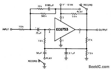
Record/playback amplifier for cassette and portable tape recorders (courtesy GTE Sylvania Incorporated). (View)
View full Circuit Diagram | Comments | Reading(599)
1_watt_class_B_audio_amplifier_with_preamplifier
Published:2009/7/20 2:27:00 Author:Jessie
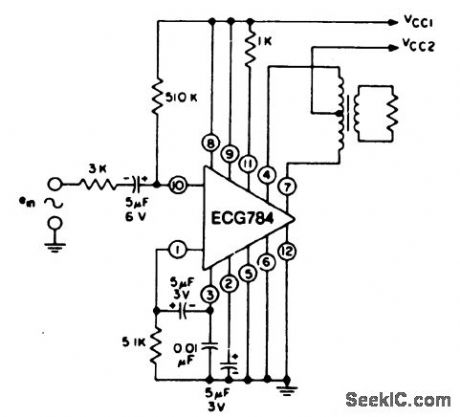
1-watt class B audio amplifier with preamplifier. Supply voltage VCC1 and VCC2 are 9.0 volts and 12.0 volts, respectively. Sensitivity is 45 mV. Power gain is 75 dB. Input resistance is 55K. Signal-to-noise ratio is 66 dB. Use a standard class B audio output transformer with the appropriate speaker load (courtesy GTE Sylvania Incorporated). (View)
View full Circuit Diagram | Comments | Reading(884)
The ADV7175 and ADV7176 digital video encoding integrated circuits
Published:2011/7/20 1:32:00 Author:Borg | Keyword: digital, video encoding, integrated circuits
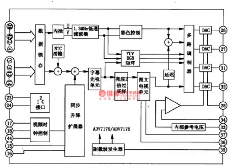
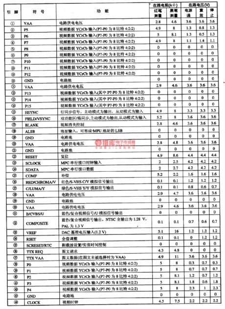
1.pin functionsADV7175 and ADV7176 integrated circuits support many standards of CCIR601/624/656 and SMPE170M, which is in I2C control method, and it can convert the YCRCB video data of 8 or 16-bit into Y, U and V in the patten of 4:4:4, and the 4 internal lObitDAC can output R, G and B, or Y, U and V, or S-VHS and Y/C or mixed video signals. It contains the low-pass filter, color control circuit YUV, RGB matrix circuit, brightness double sampling circuit, image-text TV units and so on.
(View)
View full Circuit Diagram | Comments | Reading(780)
SIREN_POWER_AMPLIFIER
Published:2009/7/9 23:31:00 Author:May
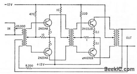
Four-transistor class AB audio amplifier delivers 200 w to four loudspeakers. Standby power drain is 12 w.Input is obtained from warble generator.-W.F. Ferguson, High-Powered Audio Alarm Systems, Electronics, 33:16, p 70-72. (View)
View full Circuit Diagram | Comments | Reading(728)
4_watt_class_A_audio_amplifier_using_an_ECG755_audio_driver_IC
Published:2009/7/20 2:26:00 Author:Jessie
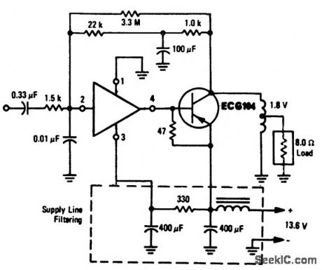
4-watt class A audio amplifier using an ECG755 audio driver IC. This audio amplifier is ideal for automotive applications. The ECG755 is a 4-lead package and is designed to drive a PNP power output transistor such as the EGG104 (courtesy GTE Sylvania Incorporated). (View)
View full Circuit Diagram | Comments | Reading(848)
025_watt_AF_amplifier_using_a_16_ohm_speaker
Published:2009/7/20 2:22:00 Author:Jessie
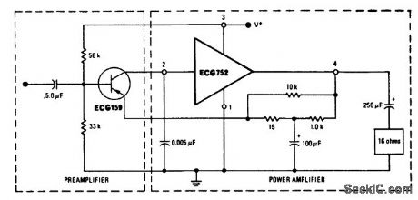
0.25-watt AF amplifier using a 16-ohm speaker. Supply voltage should be approximately 12 volts (courtesy GTE Sylvania Incorporated). (View)
View full Circuit Diagram | Comments | Reading(602)
1_watt_AF_amplifier_for_phonographs_with_ceramic_cartridges_using_a_16_ohm_speaker
Published:2009/7/20 2:21:00 Author:Jessie
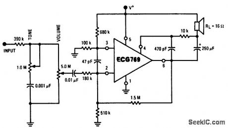
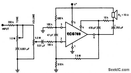
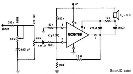
1-watt AF amplifier for phonographs with ceramic cartridges, using a 16-ohm speaker. Sensitivity is 100 mV for 1-watt output. Supply voltage should be 16 volts (courtesy GTE Sylvania Incorporated). (View)
View full Circuit Diagram | Comments | Reading(633)
05_watt_audio_amplifier_for_an_AM_FM_radio
Published:2009/7/20 2:20:00 Author:Jessie
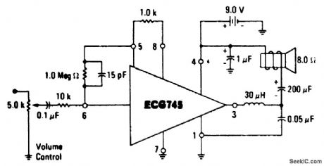
0.5-watt audio amplifier for an AM/FM radio. The ECG745 is an 8-pin DIP (courtesy GTE Sylvania Incorporated ). (View)
View full Circuit Diagram | Comments | Reading(607)
05_watt_AF_amplifier_for_a_phonograph_with_a_ceramic_cartridge
Published:2009/7/20 2:14:00 Author:Jessie
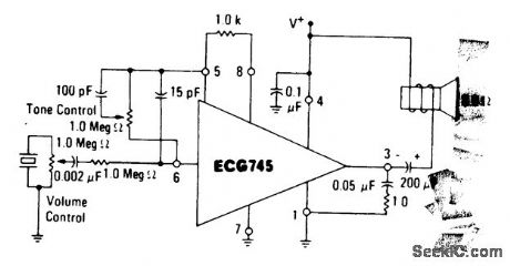
0.5-watt AF amplifier for a phonograph with a ceramic cartridge. The ECG745 is an 8-pin DIP (courtesy GTE Sylvania Incorporated). (View)
View full Circuit Diagram | Comments | Reading(653)
1_watt_phonograph_amplifier_with_an_8_ohm_speaker
Published:2009/7/20 2:11:00 Author:Jessie
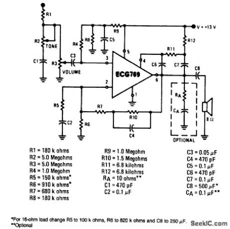
1-watt phonograph amplifier with an 8-ohm speaker. Intended for use with a ceramic cartridge. Sensitivity approximately 450 mV. The gain of the amplifier is determined by (R7+R10)/R5. To change the gain, alter the value of R5 and hold (R7+R10) between 1M and 2.2M. Bass boost can be eliminated by removing C4 and replacing (R7+R10) with a fixed resistor valued at 2.2M (courtesy GTE Sylvania Incorporated). (View)
View full Circuit Diagram | Comments | Reading(827)
2_watts_per_channel_dual_audio_amplifier_using_an_ECG804_IC
Published:2009/7/20 2:38:00 Author:Jessie
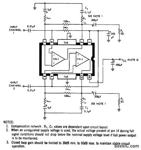
2-watts-per-channel dual audio amplifier using an ECG804 IC. For 8-ohmspeaker loads use a 20-volt supply, for 16-ohm sneaker loads use a 24-voltsupplyand for 4.ohm speaker loads use a 12-volt supply (courtesy GTE Sylvania Incorporated). (View)
View full Circuit Diagram | Comments | Reading(594)
Low_noise_AF_preamplifier
Published:2009/7/20 2:36:00 Author:Jessie
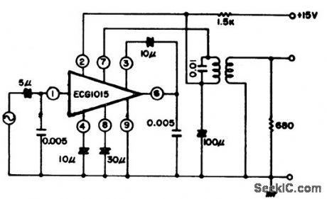
Low-noise AF preamplifier. The preamplifier provides 0.9 volts output at 1 kHz witha 2 mV input. ECG1015 is a hybrid module (courtesy GTE Sylvania Incorporated). (View)
View full Circuit Diagram | Comments | Reading(707)
HIGH_SPEED_SAMPLE_AND_HOLD
Published:2009/7/9 23:11:00 Author:May
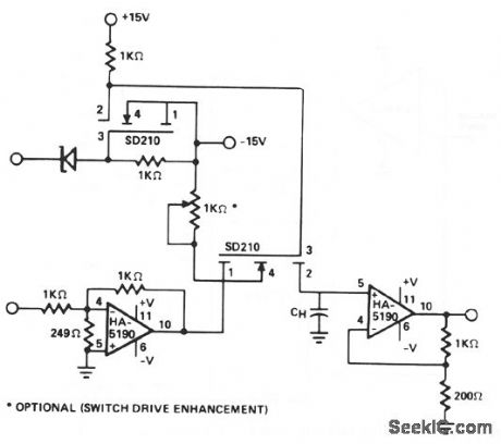
This circuit uses the speed and drive capability of the HA-5190 coupled with two high-speed DMOS FET switches. The input amplifier is allowed to operate at a gain of -5, although the overall circuit gain is unity. Acquisition times of less than 100 ns to 0.1% of a 1-V input step are possible. Drift current can be appreciably reduced by using FET input buffers on the output stage of the sample-and-hold. (View)
View full Circuit Diagram | Comments | Reading(0)
SIREN_PREAMPLI_FIER
Published:2009/7/9 23:11:00 Author:May
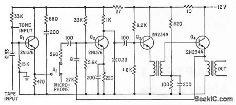
Supplies signals to remote power ampliters and loudspeakers of fire and civil defense systems. Input can be from electronic siren generator, magnetic tape, or microphone.-W. F. Ferguson, High-Powered Audio Alarm Systems, Electronics, 33:16, p 70-72. (View)
View full Circuit Diagram | Comments | Reading(692)
60_W_225-400_MHz_AMPLIFIER
Published:2009/7/9 23:06:00 Author:May
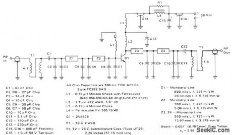
This 60-W, 28-V broadband amplifier covers the 225-400 MHz military communications band. The amplifier may be used singly as a 60-W output stage in a 225-400 MHz transmitter, or by using two of these amplifiers combined with quadrature couplers, a 100-W output amplifier stage can be constructed.The circuit is designed to be driven from a 50-Ω source and work into a nominal 50-Ω load. The input network consists of two microstrip L-sections composed of Z1, Z2, and C2 through CG. C1 serves as a dcblocking capacitor. A 4:1 impedance ratio coaxial transformer T1 completes the input matching network.L1 and a ferrite bead serve as a base decoupling choke. The output circuit consists of shunt inductor L2 at the collector, followed by two microstrip L-sections composed of Z3, Z4, and C8 through C11. C12 serves as a dc blocking capacitor, and is followed by another 4:1 impedance ratio coaxial transformer. Collector decoupling is accomplished through the use of L3, L4, C14, C15, C16, and R1. (View)
View full Circuit Diagram | Comments | Reading(800)
05_watt_OTL_audio_power_amplifier_using_an_ECG1031
Published:2009/7/20 2:41:00 Author:Jessie
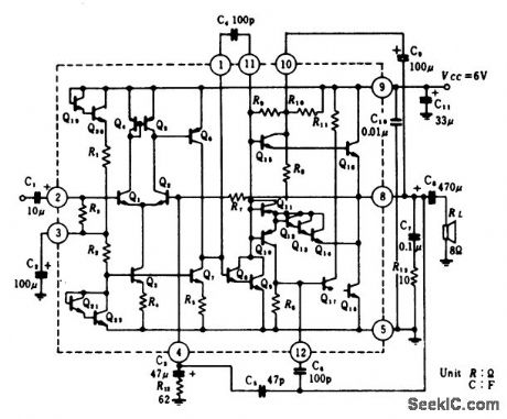
0.5-watt OTL audio power amplifier using an ECG1031. Typical voltage gain at 1 kHz is 50 dB. Input impedance is 20K (courtesy GTE Sylvania). (View)
View full Circuit Diagram | Comments | Reading(647)
4_watt_audio_power_amplifier_with_a_7_mV_sensitivity_for_automobile_applications
Published:2009/7/20 2:40:00 Author:Jessie
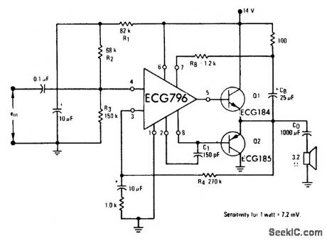
4-watt audio power amplifier with a 7 mV sensitivity for automobile applications. By changing the output transistors the output can be increased up to 20 watts (courtesy GTE Sylvania Incorporated). (View)
View full Circuit Diagram | Comments | Reading(704)
UHF_TV_PREAMPLIFIER
Published:2009/7/9 23:03:00 Author:May
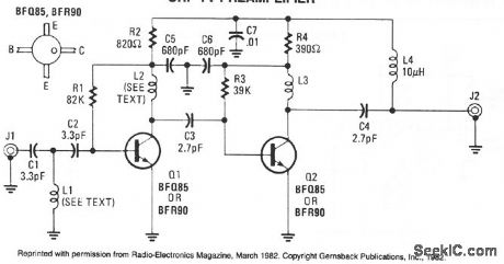
An inexpensive, antenna-mounted, UHF-TV preamplifter can add more than 25 dB of gain. The first stage of the preamp is biased for optimum noise, the second stage for optimum gain. L1, L2 strip line ≈λ/8 part of PC board. (View)
View full Circuit Diagram | Comments | Reading(5860)
| Pages:96/250 At 2081828384858687888990919293949596979899100Under 20 |
Circuit Categories
power supply circuit
Amplifier Circuit
Basic Circuit
LED and Light Circuit
Sensor Circuit
Signal Processing
Electrical Equipment Circuit
Control Circuit
Remote Control Circuit
A/D-D/A Converter Circuit
Audio Circuit
Measuring and Test Circuit
Communication Circuit
Computer-Related Circuit
555 Circuit
Automotive Circuit
Repairing Circuit