
Circuit Diagram
Index 1479
The wiper/washer system of Buick-Regal
Published:2011/7/20 Author:Borg | Keyword: wiper/washer system, air flow
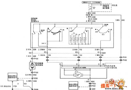
Figure 1: The wiper/washer system of Shanghai GM Buick-Regal (View)
View full Circuit Diagram | Comments | Reading(429)
The igniting system and power supply parameter circuit of Santana 2000 (32MP003182)
Published:2011/7/15 19:19:00 Author:Borg | Keyword: igniting system, power supply parameter
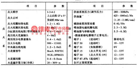
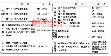
The way to test the engine electric control unit is to use the multimeter with high impedance, so the control unit won't be broken due to the parallel connection with elements in test. When the test is done, the power supply should be cut off, the igniting switch should be shut down, and the voltage and the LEV should be tested with the according voltage gear of the multimeter. To avoid breaking or loosing the computer connector terminal, a test box(equipment V.A.G1598 and cable V.A.G1598-9) is used to detect it, the terminal numbers are corresponding to the computer connector terminals.
(View)
View full Circuit Diagram | Comments | Reading(400)
The main sensor circuit of Chevrolet-Lumina (2.2L)
Published:2011/7/13 23:15:00 Author:Borg | Keyword: sensor, Chevrolet-Lumina
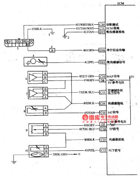
The main sensor circuit of Chevrolet-Lumina (2.2L) 1-internal/earth connection; 2-engine earth connection; 3-disconnector; 4-separating plate wire connector; 5-oxygen sensor; 6-admission pressure sensor; 7-air-conditioner refrigerant; 8-admission temperature sensor; 9-throttle position sensor; 10-coolant temperature sensor; 11-dehydrate temperature lamp (View)
View full Circuit Diagram | Comments | Reading(1351)
Minimum cost sound control music color light circuit
Published:2011/7/25 1:43:00 Author:Christina | Keyword: Minimum cost, sound control, music, color light
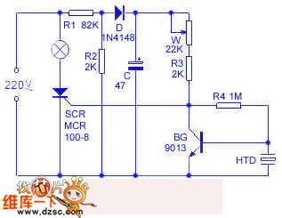
The color light controller circuit is as shown in the figure, the resistance step-down half-wave full-wave circuit is composed of the r1, r2, d and c, it outputs the 3V DC current to the control circuit of SCR. The piezoelectric ceramics htd is used as the sound-electric transducer, you can make the bg collector output the low level by adjusting w, the scr cuts off, the color light turns off. When the htd receives the acoustic signal, the electrical level of the bg collector will rise up, the scr turns on, the color light can flash with the music rhythm of the indoor radio. w can be used to adjust the sound control sensitivity, when the w is from high to low, the sound sensitivity is from low to high, when the w is too low, the light will turn on, so the circuit loss the sound control function.
(View)
View full Circuit Diagram | Comments | Reading(988)
The backup lamp and instrument circuit of Santana 2000(figure 1 and 2)
Published:2011/7/15 19:17:00 Author:Borg | Keyword: backup lamp, instrument circuit

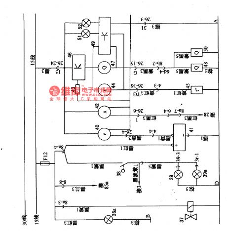
Figure1. The backup lamp and instrument circuit of Santana 2000 (gasoline injection engine)36a-light switch lighting lamp; 37-electromagnet valve; 38-backup lamp switch; 39-backup(left); 40-car speed odometer; 41-speedometer sensor; 42-engine tachometer; 34-resistor divider; 44-thermometer; 45-thermometer sensor; 46-water temperature and fuel signal amplifier; 50-fuel meter sensor(gasoline injection engine); 51-coolant alarm lamp; 52-fuel alarm lamp
(View)
View full Circuit Diagram | Comments | Reading(407)
The headlight and fog light circuit of Nanjing Iveco light car
Published:2011/7/15 19:16:00 Author:Borg | Keyword: headlight, light car
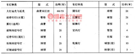
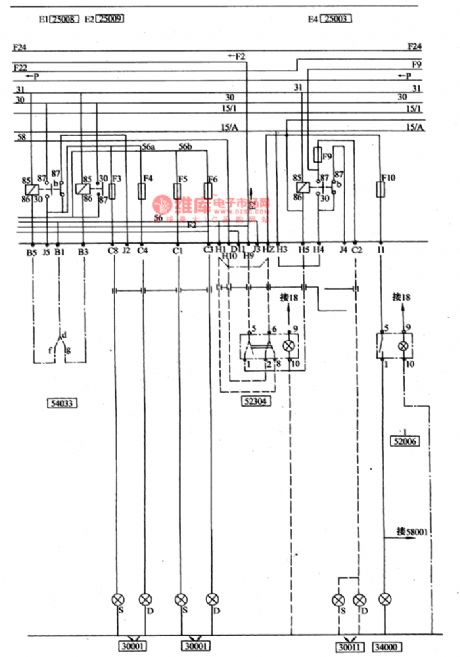
The lighting system(see as figure 3) is controlled by the external lamp switch 52307, the switch power comes from two sources, the current of the width lamp, tail lamp and license lamp is connected with No.30 wire (battery positive pole), as long as the switch is at the 1 or 2 gear, it is passable, and the current of the head light relay coil is led to cylinder 4 of switch 52307 from the igniting switch, if the igniting switch is cut off, the current can not be connected with the headlight. If the external is at 2 gear, one of the relay 25009 of high beam and the relay 25008 is closed.
(View)
View full Circuit Diagram | Comments | Reading(533)
CL484--T128--the audio/video decoding integrated circuit
Published:2011/7/15 19:15:00 Author:Borg | Keyword: audio/video decoding, integrated circuit
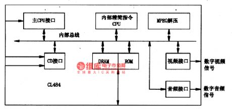
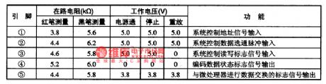
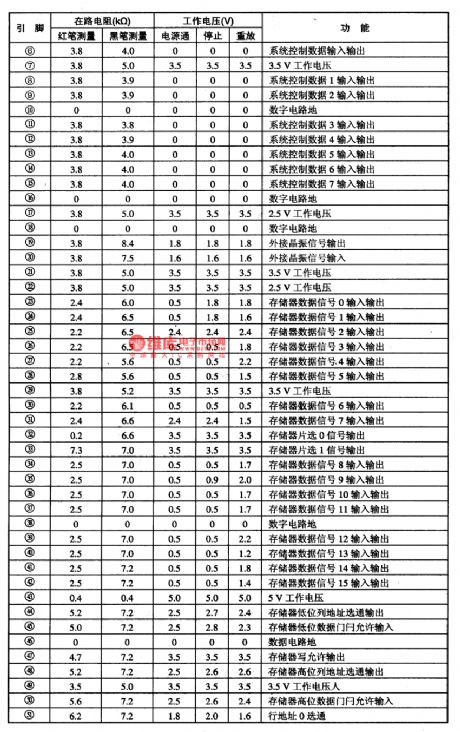
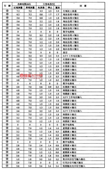
1.function featuresCU84 combines pictures and sound decoding circuit, whose main function is to switch the CD and CD-ROM mixed digit signals of MPEG-I standard compressing codes into the audio digital signals and video digital signals, so that the signals are easy to turn back to analog audio and video signals through audio and video D/A converting circuit. The circuit contains the CPU connector, CD connector, internal DRAM/ROM connector, MPEG-I decompressing unit, symbol generator (OSD), audio/video connector and other circuits. The internal circuit of the chip is shown in figure 1.
(View)
View full Circuit Diagram | Comments | Reading(621)
CMS-O01--the single chip microcomputer control integrated circuit
Published:2011/7/15 19:15:00 Author:Borg | Keyword: single chip microcomputer, integrated circuit
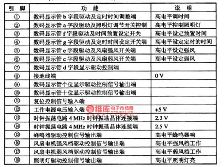
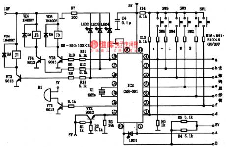
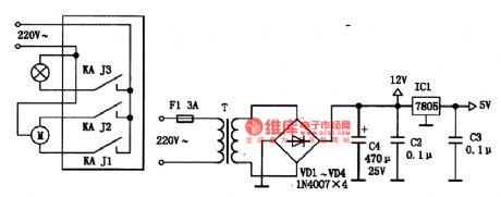
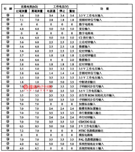
CMS-O01 is a single chip microcomputer control integrated circuit, which is widely used in the electric control systems as the main chip of all kinds of kitchen ventilators, such as Tuoli.1.function featuresCMS-O01 integrated circuit contains the CPU clock oscillating circuit, dual-bit 7-stage LED digit tube drive control circuit, reset circuit, drive control circuits all types of relays and buzzers and other affiliated function circuits.2.pin functions and dataCMS-O01 is in the 18-pin dual in-line package.
(View)
View full Circuit Diagram | Comments | Reading(491)
The air-conditioning circuit of Nanjing Iveco light car
Published:2011/7/15 19:14:00 Author:Borg | Keyword: air-conditioning circuit, light car
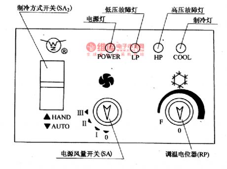
(18) The air-conditioning circuit of Nanjing Iveco light carThe air-conditioning system of Nanjing Iveco light car is in a non-independent structure, which is driven by the engine crankshaft belt with the help of compressor and electromagnetic clutch, and whether electromagnetic clutch is separated or connected is decided by the temperature control switch(manual or auto or their combination), the cooling part consists of the compressor, condenser, liquid storing tank, swelling valve, evaporator, electric control system and tube, etc. The coolant is R-12 (freon), and it refrigerates in the vapor compressing method.
(View)
View full Circuit Diagram | Comments | Reading(439)
CX2O111--the Am/Fm radio integrated circuit
Published:2011/7/15 19:14:00 Author:Borg | Keyword: Am/Fm radio, integrated circuit
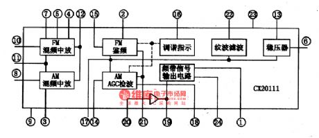

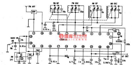
CX2O111 is the AM/FM radio integrated circuit produced by Sony, which is used in radios, recorders, compound stereos and so on.1.the internal circuit and pin functions of CX2O111CX2O111 includes all the circuits of the AM/FM and efficiency, mix, INTREQ and detected wave output audio signals. This IC is in 24-pin dual line flat package, whose internal circuit is shown in Figure 1 and the pin functions and data are listed in table 1.
Figure 1. the internal circuit of CX2O111
(View)
View full Circuit Diagram | Comments | Reading(1911)
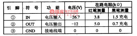
The 3-terminal voltage stabilizing integrated circuit
Published:2011/7/15 19:13:00 Author:Borg | Keyword: 3-terminal, integrated circuit
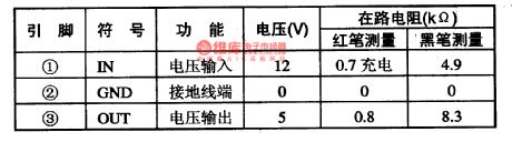
L7805 is a 3-terminal voltage stabilizing integrated circuit produced by Sanyo, which is widely used in the power supplies of all kinds of electric apparatus. When L7805 is used in Changhong Jingxian and Jingxianren projection TV sets, it pin functions and data are shown in table 1-1.
Table 1-1 the pin function and data of L7805 (View)
View full Circuit Diagram | Comments | Reading(463)
L7812--the 3-terminal voltage stabilizing integrated circuit
Published:2011/7/15 19:12:00 Author:Borg | Keyword: 3-terminal, integrated circuit

L7912 is the the 3-terminalvoltage stabilizingintegrated circuit produced by Sanyo, Japan, which is widely used in power supply circuits of all kinds of electric apparatus. When L7912 is used in Changhong clear and clear king projector color TV sets, its pin functions and data are listed in table 1-1.
Table 1-1 pin functions and data of L7812 (View)
View full Circuit Diagram | Comments | Reading(510)
L7912--the 3-terminal negative stable integrated circuit
Published:2011/7/13 23:12:00 Author:Borg | Keyword: 3-terminal, negative, stable, integrated circuit
L7912 is the 3-terminal negative stable integrated circuit produced by Sanyo, Japan, which is widely used in power supply circuits of all kinds of electric apparatus. When L7912 is used in Changhong clear and clear king projector color TV sets,its pin functions and data are listed in table 1-1.
Table 1-1 pin functions and data of L7912 (View)
View full Circuit Diagram | Comments | Reading(873)
Instrument amplifier (INA101) circuit with expandable common mode range
Published:2011/7/25 1:59:00 Author:Christina | Keyword: Instrument amplifier, expandable, common mode range

The instrument amplifier (INA101) circuit with the expandable common mode range is as shown in the figure. In this circuit, the A1, A2 and A3 are composed of the high precision instrument amplifier INA101 or INA102. In this figure, the voltage magnifications of the A1, A2 and A3 are l00 times, the post-amplifier uses the precision unit gain amplifier INA105, the connection of this amplifier is the in-phase port input and follower output model, the four resistances of the circuit are in parallel, so this INA105 amplifier can get the 2 times of voltage magnification and extremely high input impedance.
(View)
View full Circuit Diagram | Comments | Reading(1191)
Household simple flashing wall lamp controller circuit
Published:2011/7/25 2:11:00 Author:Christina | Keyword: Household, simple, flashing, wall lamp, controller

The circuit principle: the circuit is as shown in the figure, the simple resistance step-down half-wave full-wave circuit is composed of vd1, vd2, r3 and c2, it outputs the 12V DC to the IC. The multivibrator is composed of the NOT gate I and II, you can change the oscillation frequency by adjusting the rp1 and rp2. The VD3 has the isolation effect to prevent the influence between rp1 and rp2 when you are adjusting rp1. When the circuit is start-up, the NAND gate output port alternately outputs the high level and the low level. When pin-3 outputs the high level, the thyristor vs2 conducts, the light b turns on, at this time the pin-4 has the low level, the light a will not turns on; when pin-3 outputs the low level, the thyristor vs2 cuts off, the light b turns off.
(View)
View full Circuit Diagram | Comments | Reading(630)
The CXA1OO5P single chip stereo playback integrated circuit
Published:2011/7/15 19:09:00 Author:Borg | Keyword: single chip, playback
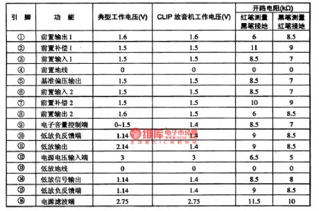


CXA1OO5P is a single chip stereo playback integrated circuit produced by Sony, which is used in ultra-small radios.1.the internal circuit and pin functions of CXA1OO5P CXA1OO5P is manufactured in dual-pole craft, which includes the preset balance amplifier, DC volume control circuit, headphone power drive stage and other function circuits. The internal circuit of the chip is shown in figure 1. The IC is in 16-pin dual in-line package, whose pin functions and data are listed in table 1.
table 1 pin functions and data of CXA1OO5P
(View)
View full Circuit Diagram | Comments | Reading(550)
The Toyota starting motor circuit
Published:2011/7/13 23:14:00 Author:Borg | Keyword: Toyota, starting motor
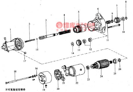
3.starting motor The Toyota-Coster bus diesel engine is installed with an electric starting motor which is electromagnetic inter meshing decelerating type, the voltage systems are 12V and 24V, the powers are 2.5kW and 4.5kW. The parameters of the starter are shown in figure 4.
(View)
View full Circuit Diagram | Comments | Reading(446)
Y-connection three-phase motor low speed running and braking in reverse circuit
Published:2011/7/14 20:29:00 Author:Lucas | Keyword: KMF, three-phase motor

Just as shown in the circuit, high-power semiconductor diode is used for lowering pressure to achieve the low-speed operation of the electric motor. When STF is pressed, AC contactor KMF pulls with the gain of electricity and the motor M runs forward. When STP is pressed, the motor M would power off. If STR is pressed at this time, diode VD1 ~ VD3 are inducted by the reverse contactors KMR. And the power is rectified. The DC current is input to three-phase stator winding. When the M does not turn, press STP for braking the M. If the motor is expected to run in alt= Y-connection three-phase motor low speed running and braking in reverse.
(View)
View full Circuit Diagram | Comments | Reading(4582)
μPC1100 control circuit, main features and pin of DC-DC circuit and power supply monitor
Published:2011/7/20 19:04:00 Author:Lucas | Keyword: control circuit, main features , pin , DC-DC circuit , power supply monitor
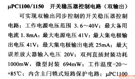
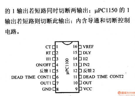
μPC1100/1150 switching regulatorcontrol circuit(dual output)
It can achieve dual output synchronous controlled switching regulator control circuit; supply voltage range is 3.6 ~ 40V; the maximum standby current is 1.8mA; the maximum supply voltage is 41V; the maximum collector output voltage is 41V; the maximum collector output current is 25mA; maximum error amplifier input voltage is 20V; dual in-line package power is 1000mW, and micro-encapsulation is 694mW; Operating Temperature is -20 ~ +85 ℃;it contains the main door short-circuit protection circuit; if μPC1100 1 output is short-circuit, the dual output should be cut off.
(View)
View full Circuit Diagram | Comments | Reading(657)
HM4246 touching stepping dimmer light
Published:2011/7/20 19:04:00 Author:Lucas | Keyword: touching stepping , dimmer light

HM4246 is the touching dimmer-specific integrated circuit which is produced by Wuxi Huafang microelectronics Co., Ltd. It has 4 dimming blocks of dark, medium, light, touch to be used as zero trigger, low high-frequency harmonic radiation. It has higher touch sensitivity and stability to adapt to a longer and higher sensor board to connect the load (400pF), which is mainly used for lamps and other lighting dimming, and the circuit is shown as the chart.
(View)
View full Circuit Diagram | Comments | Reading(841)
| Pages:1479/2234 At 2014611462146314641465146614671468146914701471147214731474147514761477147814791480Under 20 |
Circuit Categories
power supply circuit
Amplifier Circuit
Basic Circuit
LED and Light Circuit
Sensor Circuit
Signal Processing
Electrical Equipment Circuit
Control Circuit
Remote Control Circuit
A/D-D/A Converter Circuit
Audio Circuit
Measuring and Test Circuit
Communication Circuit
Computer-Related Circuit
555 Circuit
Automotive Circuit
Repairing Circuit