
Circuit Diagram
Index 1477
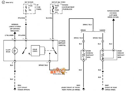
Mazda 94TAURUS demister circuit diagram
Published:2011/7/18 5:39:00 Author:nelly | Keyword: Mazda, demister
View full Circuit Diagram | Comments | Reading(600)
Mazda 94TAURUS(with DRL)headlight fog lamp circuit diagram
Published:2011/7/18 5:39:00 Author:nelly | Keyword: Mazda, headlight, fog lamp

View full Circuit Diagram | Comments | Reading(436)
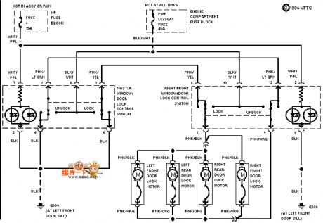
Mazda 94TAURUS(with power window)electric door lock circuit diagram
Published:2011/7/18 5:39:00 Author:nelly | Keyword: Mazda, power window, electric door lock
View full Circuit Diagram | Comments | Reading(1804)
SAA3006 general infrared remote control launch circuit
Published:2011/7/20 7:38:00 Author:Christina | Keyword: general, infrared, remote control, launch circuit


The SAA3006 is designed as one kind of low voltage power supply general general infrared remote control launch circuit. The internal circuit is composed of the oscillator, the test mode circuit, the mode selection circuit, the keyboard encoder, the control unit circuit, the decoder, the keyboard driver decoder, the instruction and system address latch and the frequency divider.
Features
Low voltage power supply, the power consumption is very small,It uses the dual-phase launch technology, the launch time is short,The single pin oscillator input,the input protection,Every launcher controls 32 systems, every system has 64 instructions,Every button of the keyboard is the single-pole switch,28-pin dual-row DIP plastic package,The matching model are TDA3048, SAA3009 and SAA3049.
(View)
View full Circuit Diagram | Comments | Reading(1218)
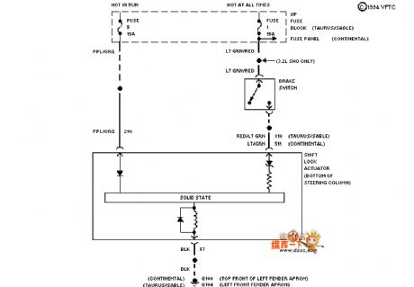
Mazda 94TAURUS shifting interlock circuit diagram
Published:2011/7/18 5:39:00 Author:nelly | Keyword: Mazda, shifting interlock
View full Circuit Diagram | Comments | Reading(586)
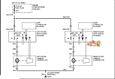
Mazda 95TAURUS electric seat waist circuit diagram
Published:2011/7/18 5:38:00 Author:nelly | Keyword: Mazda, electric seat, waist
View full Circuit Diagram | Comments | Reading(442)
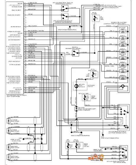
Mazda 94TAURUS(3.0L)ABS circuit diagram
Published:2011/7/18 5:40:00 Author:nelly | Keyword: Mazda, ABS
View full Circuit Diagram | Comments | Reading(377)
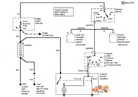
Mazda 94TAURUS(3.0L)starting circuit diagram
Published:2011/7/18 5:40:00 Author:nelly | Keyword: Mazda, starting
View full Circuit Diagram | Comments | Reading(417)
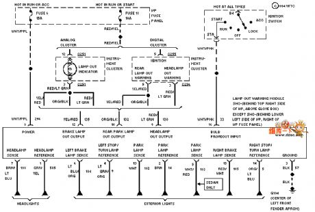
Mazda 94TAURUS(3.8L)car light monitor circuit diagram
Published:2011/7/18 5:40:00 Author:nelly | Keyword: Mazda, car light monitor
View full Circuit Diagram | Comments | Reading(522)
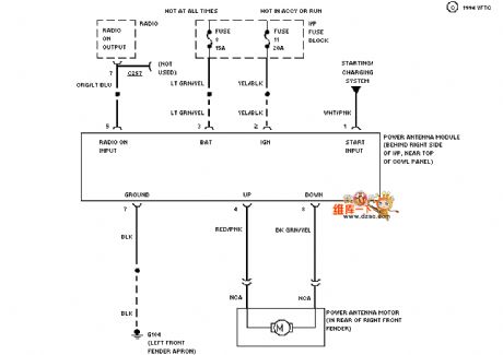
Mazda 94TAURUS electrical antenna circuit diagram
Published:2011/7/18 5:40:00 Author:nelly | Keyword: Mazda, electrical antenna
View full Circuit Diagram | Comments | Reading(432)
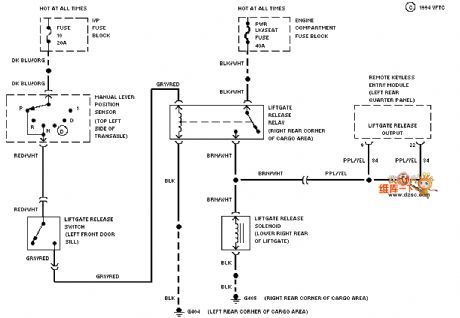
Mazda 94TAURUS back door circuit diagram
Published:2011/7/18 5:40:00 Author:nelly | Keyword: Mazda, back door
View full Circuit Diagram | Comments | Reading(391)
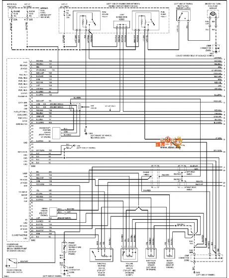
Mazda 96PROBE(2.5L) motor performance circuit diagram
Published:2011/7/18 5:40:00 Author:nelly | Keyword: Mazda, motor performance
View full Circuit Diagram | Comments | Reading(405)
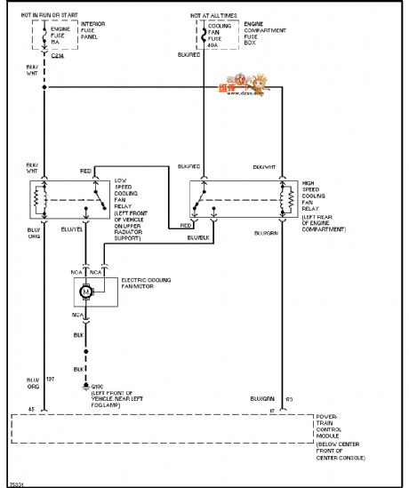
Mazda 96PROBE fan in air conditioner circuit diagram
Published:2011/7/18 5:41:00 Author:nelly | Keyword: Mazda, fan, air conditioner
View full Circuit Diagram | Comments | Reading(650)
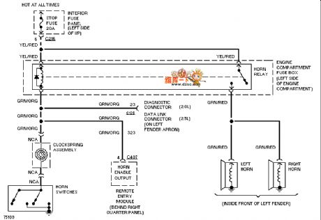
Mazda 96PROBE horn circuit diagram
Published:2011/7/18 5:41:00 Author:nelly | Keyword: Mazda, horn
View full Circuit Diagram | Comments | Reading(433)
555 musical flashing electronical ball circuit used in the game of passing hydrangea macrophylla
Published:2011/7/18 5:18:00 Author:nelly | Keyword: flashing electronical ball, game, hydrangea macrophylla
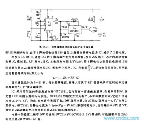
IC1 adopts the time base circuit 555, the monostable delay circuit is composed of IC1, R1, R2, RP1, C1. Before playing the game, the switch SN should be cut off, 555's 2 foot is high level( it is connected to VDD by R1), 555 is in reset state. When playing the hydrangea macrophylla, you must press SN first then pass the hydrangea macrophylla, due to 2 foot's low level, 555 is set, the high level which is outputed by 3 foot provides IC2 with working voltage.
When you arepressing SN, C1 discharges inside the chip by 555's 7 foot; after it, SN cuts off, the chip internal discharge lamp turns off, C1 is charged by R2, RP1, when C1's voltage is charged to 2/3 VDD, namely, 6 foot level reaches resetting voltage, 555 turns to reset state, 3 foot turns to low level, IC2 is no electricity and it stops phonating.
(View)
View full Circuit Diagram | Comments | Reading(1038)
DC / DC converter circuit diagram composed of NE555
Published:2011/7/24 21:57:00 Author:Ecco | Keyword: DC / DC converter

This is a converter circuit without transformer. In the circuit, power transistors VT1 ~ VT4 form the bridge circuit with alternating switch working mode, and when VT1 and VT4 are turned on, VT2 and VT3 are turned off, and it has the opposite turn in the next cycle, that is, VT2 and VT3 are turned on, and VT1 and VT4 are turned off. Bridge's A and B output AC voltage with rectangular wave, which is converted into DC voltage by the rectifier bridge VDB. NE555 is the oscillator circuit, and the oscillation frequency is decided by the R1, RP1 and C1.
(View)
View full Circuit Diagram | Comments | Reading(1271)
MC44603P switching power thick film IC diagram
Published:2011/7/24 21:51:00 Author:Ecco | Keyword: switching power , thick film IC

MC44603P switching power thick-film integrated circuit produced by Motorola which is widely used in Philips GFL movement (such as 28PW777A/93 TV), Philips PV4 · 0 movement (such as 25PT448A93S, 25V7, 25V8 TV), Philips MDl.OA and MDl.I movement (29PT446/93S, 29V8, etc.). 1. Features and functionsMC44603P IC contains oscillation error detection, drive, protection, synchronization control circuits. 2 pin functions and data MC44603P IC pin functions and data are listed in Table.
(View)
View full Circuit Diagram | Comments | Reading(1178)
The inverter circuit diagram composed of NE555
Published:2011/7/24 20:30:00 Author:Ecco | Keyword: inverter

The inverter circuit diagram composed of NE555 is shown as the chart, and it can turn +12V DC battery voltage to 220V AC output voltage. In the circuit, NE555 circuit is the oscillator, the oscillation frequency is decided by the R1, RP1 and C1, and adjusting the resistance of RP1 in 50HZ, one way of the pulse signal output by NE555's pin 3 is directly added to the base of VT2, and the other way is added to the base of VT1 by passing VT11 inverter, then VT1 and VT2 get 180 ° phase difference pulse voltage.
(View)
View full Circuit Diagram | Comments | Reading(3526)
SAA3004 infrared remote control launch circuit
Published:2011/7/20 8:15:00 Author:Christina | Keyword: infrared, remote control, launch circuit
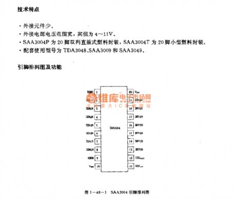


Features
The little external components.The wide external power supply voltage range, the value is 4-11V.The SAA3004P uses the 20-pin dual-row DIP plastic package, the SAA3004T uses the 20-pin small size plastic package.The matching model are TDA3048, SAA3009 and SAA3049.
Function description
The oscillating circuit has the external ceramic filter. The typical value of the reference frequency is 450kHz.When the VDD=6V, the remote control output current is the maximum.In the non-operating state, the power supply current is very small, the value is lower than 2uA; in the operating state, the power supply current is lower than 2mA.It has seven groups of subsystem addresses, every subsystem has 64 instructions.
(View)
View full Circuit Diagram | Comments | Reading(1980)
Telephone disconnection detection circuit diagram
Published:2011/7/24 21:45:00 Author:Ecco | Keyword: Telephone disconnection detection, MOSFET

The chart shows the telephone disconnection detection circuit, which is based on the offset micro power consumption oscillator provided by telephone lines, and it generates differential signals, which is added to the circuit by the high voltage capacitor. These capacitors can provide the necessary isolation, and only when the output load of the oscillator itself is negligible, the detection circuit can detect oscillation. Oscillator uses the astable multivibrator composed of VT1 and VT2. This oscillator depends on the transistor collector resistance.
(View)
View full Circuit Diagram | Comments | Reading(660)
| Pages:1477/2234 At 2014611462146314641465146614671468146914701471147214731474147514761477147814791480Under 20 |
Circuit Categories
power supply circuit
Amplifier Circuit
Basic Circuit
LED and Light Circuit
Sensor Circuit
Signal Processing
Electrical Equipment Circuit
Control Circuit
Remote Control Circuit
A/D-D/A Converter Circuit
Audio Circuit
Measuring and Test Circuit
Communication Circuit
Computer-Related Circuit
555 Circuit
Automotive Circuit
Repairing Circuit