
Circuit Diagram
Index 1474
SAA3027 general infrared remote control launch circuit
Published:2011/7/20 8:02:00 Author:Christina | Keyword: general, infrared, remote control, launch circuit


The SAA3027 is designed as one kind of general infrared remote control launch circuit. The internal circuit is composed of the oscillator, the test mode circuit, the mode selection circuit, the keyboard encoder, the control unit circuit, the decoder, the keyboard driver decoder, the instruction and system address latch and the frequency divider.
Features
Low voltage power supply, the power consumption is very small,It uses the dual-phase launch technology, the launch time is short,The input protection,The simple test mode,The oscillator is connected with the LC frequency stabilizer, there is no need of the crystal oscillator,Every button of the keyboard is the single-pole switch,28-pin dual-row DIP plastic package.
(View)
View full Circuit Diagram | Comments | Reading(884)
SAA3007 infrared remote control launch circuit
Published:2011/7/20 8:32:00 Author:Christina | Keyword: infrared, remote control, launch circuit


Features
The little external components.The low external power supply voltage, the value is 2-6.5V.The modulation frequency is 455kHz, we can use this frequency to prevent the interference of the fluorescent lamp.In the non-operating state, the power supply current is very small, the value is lower than 4uA when VDD=6V.It has 20 groups of subsystem addresses, every subsystem has 64 instructions.The instruction is transmitted with the pulse intermission pulse coding method, there are two methods: the infrared flash pulse and the modulating pulse. The infrared flash pulse requires the receiving system to use the broadband preamplifier to restrain the noise, the modulating pulse allows the receiving system to use the narrowband preamplifier to restrain the noise.The 20-pin dual-row DIP package.
(View)
View full Circuit Diagram | Comments | Reading(1497)
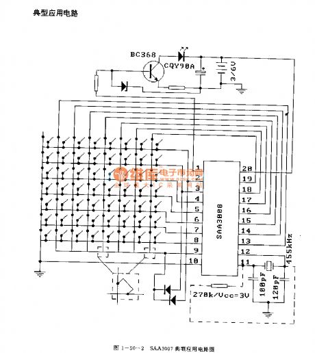
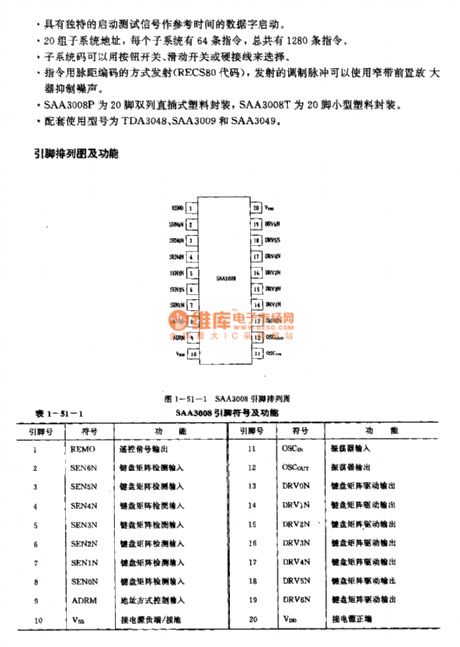
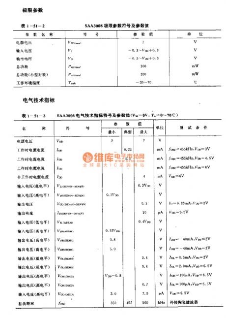
SAA3008 infrared remote control launch circuit
Published:2011/7/20 8:23:00 Author:Christina | Keyword: infrared, remote control, launch circuit

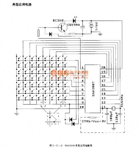
Features
The little external components.The wide external power supply voltage range, the value is 4-6.5V.The oscillating circuit has the external ceramic filter. The typical value of the reference frequency is 455kHz, the carrier-wave frequency is 1/12 of the reference frequency.In the non-operating state, the power supply current is very small, the value is lower than 4uA when VDD=6V.It has 20 groups of subsystem addresses, every subsystem has 64 instructions.The SAA3008P uses the 20-pin dual-row DIP plastic package, the SAA3008T uses the 20-pin small size plastic package.The matching model are TDA3048, SAA3009 and SAA3049.
(View)
View full Circuit Diagram | Comments | Reading(1696)
Old electric fan remote control modification
Published:2011/7/25 21:03:00 Author:Christina | Keyword: Old, electric fan, remote control, modification
(1).Remote control receiving circuit: the circuit is composed of the infrared receiver REC and the IC1 (555), in peacetime the output port of REC has the high level.
(2).Normal wind control: when the power is connected, the on-clear circuit of IC2 makes the Q0 has the high level, and the LED1 which is connected with it is lighted.
(3).Natural wind control: When you press the remote controller the 4th time, the Q4 of IC2 has the high level, the multivibrator which is composed of the IC3(555) starts oscillating.
(4).Sleep wind control: When you press the remote controller the 5th time, the Q5 of IC2 outputs the high level, the 3DG12 conducts, the J1 operates, the J1-1 closes.
(View)
View full Circuit Diagram | Comments | Reading(1023)
Electric fence control circuit 5
Published:2011/7/25 2:50:00 Author:Ecco | Keyword: Electric fence control
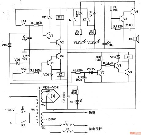
The electric fence control circuit is composed of the +6 V power supply circuit, high-voltage output circuit, trigger control circuit, alarm circuit and protection circuit, and it is shown in Figure 4-30. +6 V power supply circuit is composed of the power control button S, power transformer T, rectifier diodes VD8-VDll, filter capacitor C5, current-limiting resistor R9 and the power indicator LED VL3. Trigger control circuit consists of reeds SAl, SA2, resistors Rl, RlO, diodes VDl, VD6, transistors Vl-V4 and relays Kl, K2.
(View)
View full Circuit Diagram | Comments | Reading(3445)
Electric fence control circuit 4
Published:2011/7/25 2:47:00 Author:Ecco | Keyword: Electric fence control

The electric fence control circuit is composed of the pulse generator, high-voltage generator and undervoltage alarm circuit, and it is shown in Figure 4-29. Pulse generator circuit consists of the Dl, D2 which are inside of NAND gate Schmitt trigger IC (Dl-D4), resistors R2, R3, and capacitor Cl, diode VD2. High-voltage generator circuit is composed of the R4-R7, transistors Vl, V2, and pulse transformer T. Undervoltage alarm circuit is composed of the internal D3, D4 of IC, transistors V3, V4, voltage regulator diode VS, resistors R8-R13, capacitor C3, light emitting diode VL and buzzer HA.
(View)
View full Circuit Diagram | Comments | Reading(2239)
The photosensitive diode circuit
Published:2011/7/25 20:35:00 Author:Christina | Keyword: photosensitive diode

(a) is the black & white changing voice signal soundtrack which is recorded on the film, it is the sound motion picture. When the machinery gear drives the synchronous holes of the movie film, the light gets through the pictures, and is amplified by the projection lens to project the picture on the projection screen, this is the activity movies. When the film is moving, the soundtrack is moving too; the light which is sent out by the incentive bulb changes into a beam of light through the 0.05mm slit, and it projects to the soundtrack through the lens group.
(b) is the photosensitive diode circuit of the motion-picture machine.
(View)
View full Circuit Diagram | Comments | Reading(645)
The control switch circuit with the cd4017
Published:2011/7/25 2:26:00 Author:Christina | Keyword: control switch

The output port q2 of cd4017 is connected with the clear port cr, so the q0 and q1 outputs the high level alternately under the function of the cp port input pulse. When the power is connected, the pin-15's differential circuits r2 and c1 clear the circuit, the q0 port outputs the high level, the q1 port outputs the low level, the transistor vt cuts off, the relay k will not operate, the light h which is controlled by k will not turns on. If you press the button sb which is connected with cp in parallel, the cp port will output a positive pulse, the q0 port outputs the low level, q1 outputs the high level, the vt conducts, the relay k gets power to close, the normally open contact point closes, the light h turns on.
(View)
View full Circuit Diagram | Comments | Reading(637)
Portable emergency light circuit with the automatic stop-charging function
Published:2011/7/25 2:35:00 Author:Christina | Keyword: Portable, emergency light, automatic, stop-charging function


After the power is connected, if you press the sw1, the charging indicator light led will turn on, at this time the storage battery is lack of electricity, the e pole voltage of q1 is lower than the b pole voltage, so q1 and q2 cut off, q3 conducts to close the relay, the J1-1 closes to get in the self-locking state, J1 releases, the power cuts off, the charging stops, at the same time the charging indicator light led turns off. In the figure, the d1 is the isolation diode, it can be used to prevent the reverse discharge of the storage battery, you can make the circuit charge the storage batteries with different voltage by adjusting rw1.
(View)
View full Circuit Diagram | Comments | Reading(1728)
Simple infrared ray control lighting switch circuit
Published:2011/7/25 20:20:00 Author:Christina | Keyword: Simple, infrared ray, control, lighting switch
When you connect the power supply, the infrared emitting diode d6 sends out the infrared ray, and the phototransistor q1's c-e pole is in the low resistance state under the infrared light irradiation, and the q2's base electrode b is in the high level state, q2 conducts. Then q3 and q4 conduct. q5's base electrode b has the low level and is in the cut-off state because the q4 is conducted, the relay will not operate. When the person or object cuts off the infrared beam of d6, the q1's c-e pole is in the high level state, then q2, q3, q4 cut off, q5 conducts, the relay operates to turn on the light.
(View)
View full Circuit Diagram | Comments | Reading(1162)
Electric fence control circuit 8
Published:2011/7/25 2:35:00 Author:Ecco | Keyword: Electric fence control

The electric fence control circuit is composed of the power supply circuit, self-oscillating circuit, trigger control circuit, high voltage circuit and alarm circuit, and it is shown in Figure 4-33. Power supply circuit is composed of the battery GB, power switch Sl, voltmeter PV, ammeter PA, filter capacitor Cl, inductor L and isolation diode VDg. Self-oscillation circuit is composed of the electronic switch integrated circuit ICl, resistors Rl-R5, R8, R9, capacitors C2-C4, potentiometer RPl, diodes VDl, VD2 and oscillation transformer Tl.
(View)
View full Circuit Diagram | Comments | Reading(4546)
Electric fence control circuit 9
Published:2011/7/25 2:32:00 Author:Ecco | Keyword: Electric fence control

The electric fence control circuit is composed of the power supply circuit, trigger control circuit, high voltage circuit and alarm circuit, and it is shown in Figure 4-34. Power supply circuit is composed of the power switch Sl, voltmeter PV, fuse FU, resistors Rl, Rg, power indicators HLl, HL2, power transformer Tl, rectifier bridge piles URl-UR3, capacitors Cl, C5, C8, inductor L, ammeter PA, diode VD4 and regulator diode VS. Rl-Rll select 1/4W metal film resistors or carbon film resistors.
(View)
View full Circuit Diagram | Comments | Reading(2040)
Coop automatic controller
Published:2011/7/25 2:27:00 Author:Ecco | Keyword: Coop automatic controller
The coop automatic controller circuit is composed of the power supply circuit, humidity measurement control circuit, light detection control circuit and temperature detection control circuit, and it is shown in Figure 4-38. Power supply circuit is composed of the power transformer T, bridge rectifier URl, LED HL, three-terminal regulator IC and integrated filter capacitor Cl. Humidity measurement control circuit consists of resistor RS, bridge rectifier UR2, potentiometer RPl, transistors Vl, V2, diodes VDl, VD2, resistors Rl-R4, capacitors C2 and relay K1.
(View)
View full Circuit Diagram | Comments | Reading(523)
Temperature controller for chicken farm
Published:2011/7/25 2:22:00 Author:Ecco | Keyword: Temperature controller , chicken farm
The temperature controller circuit for chicken farm consists of temperature detection circuit, temperature control circuit and temperature simulation display circuit, and it is shown in Figure 4-39. Temperature detection circuit is composed of the integrated temperature sensor ICl, operational amplifier integrated circuit lC2 (Nl, N2), the N3, N4 which are inside of IC3 (N3-N5), resistors Rl-RlO and potentiometer RPl. Temperature control circuit is composed of internal N5 of IC3, diodes VDl, VD2, dual time-base IC lC4, resistors Rl2-Rl5, light-emitting diodes VLll, VLl2, potentiometer R and relay K.
(View)
View full Circuit Diagram | Comments | Reading(507)
Thermostat controller for farm
Published:2011/7/25 2:12:00 Author:Ecco | Keyword: Thermostat controller , farm

The thermostat circuit for farm is composed of the power supply circuit and constant temperature control circuit, and the circuit is shown in Figure 4-40. Power supply circuit is composed of the power switch S, fuse FU, power transformer T, bridge rectifier UR, filter capacitors Cl, C2, and three-terminal voltage regulator integrated circuit IC. Constant temperature control circuit is composed of the electric contact thermometer Q, relay K, intermediate relay KA, AC contactor KM, electric heater EH and heating indicator light HL. Cl and C2 select the aluminium electrolytic capacitors with the voltage above 35V.
(View)
View full Circuit Diagram | Comments | Reading(544)
SS0622 Touching stepping dimmer circuit
Published:2011/7/24 22:46:00 Author:Ecco | Keyword: Touching stepping dimmer

Touching stepping dimmer composed of the SS0622 IC is shown as the chart, and it canprovidetwo ways of four-gear stepping touching dimmeraccording to the needs of the users.
(View)
View full Circuit Diagram | Comments | Reading(939)
First-order active low-pass RC circuit diagram
Published:2011/7/24 22:39:00 Author:Ecco | Keyword: First-order , active low-pass RC

View full Circuit Diagram | Comments | Reading(505)
Second-order active low-pass RC circuit diagram
Published:2011/7/24 22:40:00 Author:Ecco | Keyword: Second-order , active low-pass RC

View full Circuit Diagram | Comments | Reading(435)
Electric fence control circuit 3
Published:2011/7/25 2:42:00 Author:Ecco | Keyword: Electric fence control

The electric fence control circuit is composed of the power supply circuit, self-excited multivibrator and high-voltage generator circuit, and it is shown in Figure 4-28. Power supply circuit is composed of the fuse FU, power transformer Tl, bridge rectifier UR, filter capacitor Cl, battery GB, power switches S1, S2. Self-excited multivibrator circuit consists of transistors Vl, V2, resistors Rl, R2, diodes VDl, VD2, and the oscillation step-up transformer T2. The high-voltage generator circuit is composed of thyristor VT, two-way trigger diode V3, resistors R3, R4, capacitors C2, C3, and step-up pulse transformer T3.
(View)
View full Circuit Diagram | Comments | Reading(5489)
Electric fence control circuit 2
Published:2011/7/25 2:38:00 Author:Ecco | Keyword: Electric fence control

Electric fence control circuit is composed of the power supply circuit, pulse generator and high-voltage circuit, and it is shown in Figure 4-27. Power supply circuit is composed of the power transformer Tl, rectifier diodes VDl, VD2, filter capacitors Cl, C2 and resistor Rl. Pulse generator is composed of the time-base integrated circuit IC, resistor m, R3 and capacitor C3. High-voltage circuit consists of step-up transformer T2, SCR VT, resistors R4, R5, capacitor C5, diode VD3 and spark gap Fl.
(View)
View full Circuit Diagram | Comments | Reading(3631)
| Pages:1474/2234 At 2014611462146314641465146614671468146914701471147214731474147514761477147814791480Under 20 |
Circuit Categories
power supply circuit
Amplifier Circuit
Basic Circuit
LED and Light Circuit
Sensor Circuit
Signal Processing
Electrical Equipment Circuit
Control Circuit
Remote Control Circuit
A/D-D/A Converter Circuit
Audio Circuit
Measuring and Test Circuit
Communication Circuit
Computer-Related Circuit
555 Circuit
Automotive Circuit
Repairing Circuit