
Circuit Diagram
Index 1470
Timing controller circuit diagram 4
Published:2011/7/26 2:08:00 Author:Ecco | Keyword: Timing controller

The timing controller circuit is composed of the power supply circuit, input control circuit, timing circuit and output control circuit, and it is shown as the chart. The power supply circuit is composed of the step-down capacitor C6, discharge resistor R6, bridge rectifier UR, filtering capacitors C5, C4 and the voltage regulator diode VS. The input control circuit is composed of the piezoelectric ceramic BC on electronic alarm clock, capacitor C1, resistors RI, transistor VI. Timing circuit consists of resistors R1 ~ R5, reset button S1, regular timing switch S2, capacitors C2 and C3, light-emitting diode VL, time-based integrated circuit IC.
(View)
View full Circuit Diagram | Comments | Reading(523)
Timing controller circuit diagram 5
Published:2011/7/26 2:12:00 Author:Ecco | Keyword: Timing controller

The timing controller circuit is composed of the power regulator circuit, timing time selection circuit, Schmitt trigger circuit and delay control circuit, and it is shown as the chart. Power regulator circuit consists of the start button S1, power transformer T, bridge rectifier UR, filter capacitor C1 and three-terminal voltage regulator integrated circuit IC1. Timing time is composed of selector switch S2, resistors R1 ~ R7. R1 ~ R16 select the 1/4W carbon film resistors. VD chooses the 1N4148 silicon switch diode.
(View)
View full Circuit Diagram | Comments | Reading(570)
Timing controller circuit diagram 6
Published:2011/7/26 2:15:00 Author:Ecco | Keyword: Timing controller

The timing controller circuit is composed of the power supply circuit, timing control circuit and control implementation circuit, and it is shown as the chart. Power supply circuit is composed of the power switch S1, fuse FU, power transformer T, rectifier diodes VD1 ~ VD4, filter capacitors C4, C5, and three-terminal voltage regulator integrated circuit IC1. Timing controller circuit is composed of the time-base circuits IC2, IC3, resistors R1 ~ R1O, capacitors C1 ~ C3, potentiometers RP1, RP2, transistors V1 ~ V4, light-emitting diodes VL1, VL2, manual discharge button S2 and function selector switch S3.
(View)
View full Circuit Diagram | Comments | Reading(602)
Darlington power transistor driver circuit diagram
Published:2011/7/26 2:00:00 Author:Ecco | Keyword: MOSFET, Darlington , power transistor, driver circuit

Bipolar power transistor (GTR or BJT) is the transistor with ice ball structure, and its junction temperature is up to 200 ℃, and under the aerospace with extremly serious environmental conditions, it has other advantages which can not be replaced. In addition, GTR has lower on-state saturation voltage drop than ICBT and MOSFET under high voltage, high current (under 10A load current, the on-state saturation voltage is less than 0.2V), it can maximize to improve the efficiency of the convertion.
(View)
View full Circuit Diagram | Comments | Reading(1660)
TP50981N microcomputer dial IC diagram
Published:2011/7/25 22:36:00 Author:Ecco | Keyword: microcomputer dial IC

TP50981N microcomputer dial IC is used in communication telephone. 1. Features and functionsTP50981N IC includes dial-up signal processing circuit, key switch signal encoding and decoding circuit, mute circuit. 2. pin function TP50981N IC pin functions are listed in Table 1-1.
(View)
View full Circuit Diagram | Comments | Reading(631)
LA7550 medium IC diagram
Published:2011/7/25 22:59:00 Author:Ecco | Keyword: medium IC
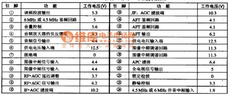
LA7550 medium IC produced by Sanyo is widely used in Hitachi series of large-screen TV, movement and the picture and sound IF signal amplification and processing in other domestic large-screen. 1. Features and functionsLA7550 IC contains the image and audio signal processing circuit, AGC control circuit, squelch control circuit, AFT automatic frequency control circuit. 2. pin functions and data LA7550 IC pin functions and data are listed in Table 1.
(View)
View full Circuit Diagram | Comments | Reading(702)
LA7910 frequency range decoding IC
Published:2011/7/25 22:27:00 Author:Ecco | Keyword: frequency range decoding

LA7910 frequency range decoding IC produced by Sanyo is widely used in a variety of screen color TV. 1. Features and functions LA7910 IC includes three-way electronic switching circuit, frequency range decoding circuit and so on. 2. pin functions and data LA7910 IC uses a separate 9-pin package, and the integrated circuit pin functions and data are listed in Table 1.
(View)
View full Circuit Diagram | Comments | Reading(941)
Primary timing controller 1
Published:2011/7/26 2:58:00 Author:Ecco | Keyword: primary timing controller

The primary timing controller circuit consists of the clock generator, divider, programming unit, driver controller and alarm, etc., and it is shown in Figure 3-83. Clock generator circuit is composed of an internal time-base circuit of the dual time-base integrated circuit ICl and the resistors R2 and R3, potentiometer RP, capacitor Cl and so on. Divider is a dual decade counter integrated circuit IC2. Programmer is reversible counter IC IC3, and 1C4 take into decimal subtraction counter IC. Drive control circuit consists of transistors Vl and V2, resistors Rl5 and Rl, diode VDl and relay K.
(View)
View full Circuit Diagram | Comments | Reading(1492)
Primary timing controller 2
Published:2011/7/26 3:01:00 Author:Ecco | Keyword: Primary timing controller

The timing controller circuit consists of the power supply circuit, input control circuit, timing circuit and output control circuit and other components, and it is shown in Figure 3-84. The power supply circuit is composed of step-down capacitor C6, resistor R6, bridge rectifier UR, filtering capacitors C5, C4 and three terminal integrated voltage regulator IC2. Input control circuit consists of the capacitor Cl, transistor Vl, resistor Rl and switch Sl. Timing circuit consists of the time-base integrated circuit ICl and the external components. Output control circuit consists of transistor V2, relay K and diode VD and other components.
(View)
View full Circuit Diagram | Comments | Reading(791)
Primary timing controller 3
Published:2011/7/26 3:04:00 Author:Ecco | Keyword: Primary timing controller

The primary timing controller circuit is composed of the power supply circuit and timing control circuit, and it is shown in Figure 3-85. Step-down power supply circuit is composed of the capacitor Cl, resistors Rl, R2, voltage regulator diodes VS, rectifier diode VD and filter capacitor C2. Timing control circuit consists of lC, control buttons Sl, S2, capacitors C3-C7, resistors R3-R5, quartz crystal oscillators BC, thyristor VT and light-emitting diodes VLl-VL6. Rl and R5 select the 1/2W carbon film resistors or metal film resistors.
(View)
View full Circuit Diagram | Comments | Reading(746)
Primary timing controller 4
Published:2011/7/26 3:07:00 Author:Ecco | Keyword: Primary timing controller

The primary timing controller circuit is composed of the power regulator circuit, timing time selection circuit, Schmitt trigger control circuit and delay circuit, and it is shown in Figure 3-86. Power supply regulator circuit consists of the start button Sl, power transformer T, bridge rectifier UR, filter capacitor Cl and three-terminal voltage regulator integrated circuit ICl. Timing time selection circuit is composed of selector switch S2 and resistors Rl-R7. Delay circuit consists of capacitors C2, C3, resistors R9, RlO, normally closed contacts K3, K4 of relay K and NOT gate integrated circuit IC2 (Dl-D4).
(View)
View full Circuit Diagram | Comments | Reading(593)
Electric curtain controller 1
Published:2011/7/26 2:27:00 Author:Ecco | Keyword: Electric curtain controller

The electric curtain controller circuit is composed of the power supply circuit, timer circuit, interlock switching circuit and overtravel-limit switch control circuit, it is shown as Figure 3-126. Power supply circuit is composed of button switches S1-1, S2-1, power transformer T, rectifier diodes VD1-VD4, capacitors C1-C4 and three-terminal voltage regulator integrated circuit ICl and so on. The timer circuit is composed of the time-base timer IC IC2, capacitor C5, resistors Rl, R2, transistor V and relay Kl. Interlock switch circuit is composed of the relay K3, and switches S1-2, S2-2, S3 and so on.
(View)
View full Circuit Diagram | Comments | Reading(1324)
Electric curtain controller 2
Published:2011/7/26 2:30:00 Author:Ecco | Keyword: Electric curtain controller

The electric curtain controller circuit is composed of the working status indication circuit, control circuit and motor drive circuit, and it is shown as Figure 3-127. Control circuit is composed of the slider switch S1, button S2, decimal counter IC and the external components. Motor drive circuit is composed of the motor M, drive transistors Vl-V6 and resistors R4-Rll. Resistor Rl2 and light-emitting diodes VLl, V form a working status indication circuit. Rl-Rl2 select 1/4W carbon film resistors.
(View)
View full Circuit Diagram | Comments | Reading(1873)
Electric curtain controller 3
Published:2011/7/26 2:34:00 Author:Ecco | Keyword: Electric curtain controller

The electric curtain controller circuit is composed of the power supply circuit, switching circuit and other components, and it is shown in Figure 3-128. Power supply circuit consists of the power transformer T, bridge rectifier UR and filter capacitor Cl. Relays Kl, K2 and limit switch S3 form the interlocking power supply polarity switching circuit. M is the drive motor, HL is the light. Sl (CKDA) and S2 (moving together) is the button. Cl, C2 select the aluminum electrolytic capacitors with the voltage in 25V. S1, S2 select the small-scale micro-button switch.
(View)
View full Circuit Diagram | Comments | Reading(519)
The field output circuit composed by discrete component
Published:2011/7/14 23:15:00 Author:Fiona | Keyword: field output circuit, discrete component

The field output circuit composed by OTL discrete component is widely used in a variety of brands machine(Usually used in 25 or below 25 inches machine), although the circuit bit numbers are not all the same, but the Circuit programs are selfsame,it can be referenced in repairs. (View)
View full Circuit Diagram | Comments | Reading(533)
Temperature controller circuit diagarm 1
Published:2011/7/25 22:16:00 Author:Ecco | Keyword: Temperature controller

The power supply circuit is composed of the step-down capacitor C1, discharge resistor RI, rectifier diodes VD1, YD2, filter capacitor C2 and zener diode VS. Temperature detection control circuit is composed of the thermistor RT, resistors R2, R3, potentiometer RP, light-emitting diode YL, three-terminal precision regulator integrated circuit IC and thyristor VT. RI selects the l/2W metal film resistor: R2 and R3 select the l/4W metal film resistor. RP uses the multi-turn potentiometer. vs uses the 2DW7 silicon zener diode.
(View)
View full Circuit Diagram | Comments | Reading(563)
Temperature controller 5
Published:2011/7/25 21:39:00 Author:Ecco | Keyword: Temperature controller

The temperature controller circuit is composed of the power supply circuit and temperature detection control circuit, and it is shown as the chart. Power supply circuit is composed of the power switch S, fuse FU, power transformer T, rectifier diodes VD1 ~ VD4, three-terminal voltage regulator integrated circuit IC1, resistors RI and limiting resistor RI, power indicator LED VL1. Temperature detection control circuit is composed of the temperature sensing diode VD5, potentiometer RP, electronic switch integrated circuit IC2, relay K, diode VD6, resistor R2 and LED VL2.
(View)
View full Circuit Diagram | Comments | Reading(452)
The circuit using NPN tube and voltage adjuster to realize the control of constant voltage and constant current
Published:2011/7/19 8:47:00 Author:Fiona | Keyword: NPN tube and voltage adjuster, constant voltage and constant current
The circuit using NPN tube and voltage adjuster to realize the control of constant voltage and constant current is shown as above:
(View)
View full Circuit Diagram | Comments | Reading(454)
Temperature controller circuit diagarm 2
Published:2011/7/25 22:19:00 Author:Ecco | Keyword: Temperature controller

Power supply circuit is composed of the power switch s, fuse FU, power transformer T, rectifier diodes VD1 ~ VD4, filter capacitor C1 and three-terminal regulator integrated circuit IC1. Temperature detection control circuit is composed of the thermistor RT, voice control integrated circuit IC2, transistor V, relay K, capacitors C2, C3, resistors RI ~ R3 and LEDs YL1, VL2. RI uses the 1/4W carbon film resistor or metal film resistor; R2 and R3 select the 1/2W carbon film resistors.
(View)
View full Circuit Diagram | Comments | Reading(523)
Low-noise RF - IF amplifier circuit diagram
Published:2011/7/25 22:08:00 Author:Ecco | Keyword: Low-noise RF amplifier, IF amplifier

The circuit is composed of two 8FZ30 integrated circuits with wide frequency bandwidth, low noise. The main properties: voltage gain Gu = 40dB; bandwidth BW = 20 to 40MHz; input signal is 5μV to 50mV.
(View)
View full Circuit Diagram | Comments | Reading(1192)
| Pages:1470/2234 At 2014611462146314641465146614671468146914701471147214731474147514761477147814791480Under 20 |
Circuit Categories
power supply circuit
Amplifier Circuit
Basic Circuit
LED and Light Circuit
Sensor Circuit
Signal Processing
Electrical Equipment Circuit
Control Circuit
Remote Control Circuit
A/D-D/A Converter Circuit
Audio Circuit
Measuring and Test Circuit
Communication Circuit
Computer-Related Circuit
555 Circuit
Automotive Circuit
Repairing Circuit