
Circuit Diagram
Index 1467
Multifunctional Adjustable Generalized Time Relay(NE555,CD4013) Circuit
Published:2011/7/23 6:06:00 Author:Sue | Keyword: Multifunctional, Adjustable, Generalized Time Relay

The circuit's multifunction means that it can acheive the three working modes conversions of delayed connection , delayed release , delayed loop . Delayed connection means that after the relay is preset, the relay isn't connected. Only when it reaches the preset timing time can it be connected. Delayed release is just the opposite to delayed connection. After the preset, the relay is connected. When it reaches the preset timing time, the relay is released. The operations of the two working modes of delayed connection and delayed release are one-time. When the relay completes one working process, the circuit's control part will enter into a stable state. (View)
View full Circuit Diagram | Comments | Reading(1043)
RC-π Type Filter Circuit
Published:2011/7/20 20:39:00 Author:Sue | Keyword: Filter

The figure shows RC-π type filter circuit. (View)
View full Circuit Diagram | Comments | Reading(714)
Multiplying Circuit 3(LM101A,HA2-2520)
Published:2011/7/22 5:38:00 Author:Sue | Keyword: Multiplying Circuit

The picture shows the multiplying circuit. A1 composes voltage-control current source. A2 composes voltage comparator. A3 composes active low pass filter. When the time constant R1C1 is equal to the clock pulse period, the relation between the input and output is: Vo=-V1V2/E. If E =1V, then Vo=-V1V2. V1,V2 are required to be positive and should be limited within 10V. V1 should be slightly lower than E. The resistor R1,R2 and capacitor C1 are required to use components with good temperature stability. A1 is HA2-2520. A2,A3 is LM101A. (View)
View full Circuit Diagram | Comments | Reading(599)
Touch Power Supply Switch Circuit Composed of CD4013
Published:2011/7/20 20:30:00 Author:Sue | Keyword: Touch, Power Supply, Switch

As seen in the figure, CD4013 can compose touch switch, which can be connected by being touched once. Another touch can make it disconnected. (View)
View full Circuit Diagram | Comments | Reading(2604)
Polo Power Steering System Circuit
Published:2011/7/26 10:16:00 Author:Robert | Keyword: Polo, Power, Steering System

The picture shows the Polo power steering system circuit.
In this circuit the D is ignition/starting switch. The G250 is power steering sensor. The J285 is the dashboard ECU with monitor. The J500 is power steering ECU. The J519 is car network ECU. The K92 is assistance mechanism signal lamp. The S164 is fuse. The SB7 is fuse 7 on the fuse holder. The T2B is plug with 2 holes. The T3e is plug with 3 holes. The T4r, T4L are plugs with 4 holes. The T11a is plug with 11 holes. The T11b is plug with 11 holes. The T16a is plug with 16 holes. The T32a is plug with 32 holes. The V119 is steering hydraulic pump. And so on. (View)
View full Circuit Diagram | Comments | Reading(3677)
LA4275 Circuit
Published:2011/7/26 4:52:00 Author:Robert | Keyword: Circuit

Overhauling notes.
(1)This chip's recommended working voltage is 27V DC voltage on pin 3 for input.
(2)The pin 4 is connected to a external 100uF/16V ripple suppression filter capacitor. If the capacitor has the cases of serious electric leakage or too low capacity, the ripple suppression performance would become bad and this would cause the alternating Weng Weng sound. In general test this pin's DC voltage should be stable 14V. (View)
View full Circuit Diagram | Comments | Reading(1346)
LA4225 Circuit
Published:2011/7/26 2:09:00 Author:Robert | Keyword: Circuit

Overhauling notes:
(1)This IC's recommended working power voltage is 18V on pin 5 for input.
(2)If there is fully no accompanying sound, it should firstly check if the pin 5's power supply is normal and then check the if the loading have the short circuit.
(3)If the pin 5's external circuit is not good, it would cause the alternating Weng, Weng sound. (View)
View full Circuit Diagram | Comments | Reading(8298)
The radiation thermometer circuit composed of NJL9102F/9103 sensors
Published:2011/7/20 0:38:00 Author:Borg | Keyword: radiation thermometer

This is the radiation thermometer circuit composed of NJL9102F/9103 sensors. NJL9102F/9103 is a sensor which combines the thermopile and the temperature compensation diode, compared to the traditional thermopile, the circuit is simple and the temperature compensation effect is better. In figure (a) is a simple radiation thermometer circuit. In the circuit, the internal resistance of the sensor is high, which is about 500kΩ. A1 is a computing amplifier with high impedance and any kind of FET input type is OK.
(View)
View full Circuit Diagram | Comments | Reading(1372)
The thermometer circuit composed of MAX6577 integrated temperature sensors
Published:2011/7/20 0:29:00 Author:Borg | Keyword: thermometer circuit, temperature sensors

This is the thermometer circuit composed of MAX6577 integrated temperature sensors, the tested temperature range is 40一+125℃. Both RP1 and RP2 are used to regulate the deviation of the output voltage U. For example, the ℃ thermometer requires the output change to be lOmV/℃, when it is 0℃, by adjusting RP1, the output will be 0V; when it is -10℃, by adjusting RP2, the output will be -1OOmV.
MAX6577 outputs square waves whose frequency is in positive proportion to the thermodynamics temperature. (View)
View full Circuit Diagram | Comments | Reading(571)
Car Multi-Function Alarm Circuit
Published:2011/7/26 10:32:00 Author:Robert | Keyword: Car, Multi-Function, Alarm

Functional requirements: When the car has got one of the malfunctions which could be detected by the system and the system would have the voice prompt alarm.Voices: left-front wheel; right-front wheel; left-rear wheel; right-rear wheel; right-rear wheel; too low tire pressure; too high tire pressure; please change battery; ding-dong.Control ways: parallel mode.voices' corresponding address: (it is added a 200ms mute case between every voice's combination)00H ding-dong + left-front wheel + too high tire prssure.01H ding-dong + right-front wheel + too high tire prssure.02H ding-dong + left-rear wheel + too high tire prssure.03H ding-dong + right-rear wheel + too high tire prssure.04H ding-dong + left-front wheel + too low tire prssure.05H ding-dong + right-front wheel + too low tire prssure.06H ding-dong + left-rear wheel + too low tire prssure.07H ding-dong + right-rear wheel + too low tire prssure.08H ding-dong + left-front wheel + please change battery.09H ding-dong + right-front wheel + please change battery.0AH ding-dong + left-rear wheel + please change battery.0BH ding-dong + right-rear wheel + please change battery.The circuit's principle diagram is shown in the pictrue. (View)
View full Circuit Diagram | Comments | Reading(857)
Photoelectric Sensor Of Tracking White Line Circuit
Published:2011/7/26 4:59:00 Author:Robert | Keyword: Photoelectric Sensor, Tracking, White, Line
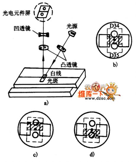
The picture shows the photoelectric sensor of tracking white line circuit.
Part (a)shows the diagram. Part (b)shows themiddle line. Part (c) shows the left-deviation line. Part (d) shows the right-deviation line. (View)
View full Circuit Diagram | Comments | Reading(953)
Eddy Current Sensor Principle Circuit
Published:2011/7/20 9:27:00 Author:Robert | Keyword: Eddy Current, Sensor, Principle
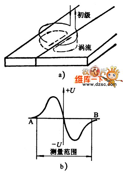
The picture shows the eddy current sensor principle circuit.
The pictureshows theeddy current distribution. The picture b shows the sensitivity curve. The U is signal voltage. (View)
View full Circuit Diagram | Comments | Reading(1321)
Contacting Two-Dimensional Tracking System Device Circuit
Published:2011/7/20 9:16:00 Author:Robert | Keyword: Contacting, Two-Dimensional, Tracking, System, Device

The picture shows the contacting two-dimensional tracking system device circuit.
The part 1 is control box. The part 2 is sensor bracket. The part 3 is the sensor. The part 4 is workpiece. The part 5 is horizontal adjustable sliding board. The part 6 is hight adjustable sliding board. The part 7 is welding head. (View)
View full Circuit Diagram | Comments | Reading(595)
The electric thermometer circuit composed of LM134
Published:2011/7/20 0:10:00 Author:Borg | Keyword: electric thermometer
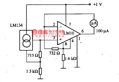
This is the electric thermometer circuit composed of LM134. In the circuit, the voltage or current output by LM134 is in proportion to the thermodynamics temperature, which can be read out on the 100μA meter, the test temperature range of the meter is -55一150℃. The power supply can work even when the voltage is under 1V, but when the precision requirement is high, the power supply should be 1.5V. When the power supply voltage is in the range of 1·5-1·2V, the inaccuracy is about 1℃.
(View)
View full Circuit Diagram | Comments | Reading(1986)
Electronic Sensor Principle Circuit
Published:2011/7/20 9:23:00 Author:Robert | Keyword: Electronic, Sensor, Principle
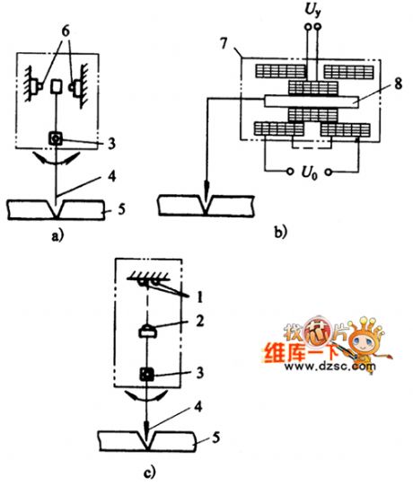
The picture shows the electronic sensor principle circuit.
The picture a is mechanical-switching type. The picture b is mechanical-differential transformer type. The picture c is mechanical-optical type.
The part 1 is photoelectric tube. The part 2 is LED. The part 3 is lever axis. The part 4 is tracking probe. The part 5 is workpiece. The part 6 is micro switch. The part 7 is displacement sensor. The part 8 is iron core. (View)
View full Circuit Diagram | Comments | Reading(956)
The self-motivation switch regulated power supply (1)
Published:2011/7/21 1:37:00 Author:Borg | Keyword: self-motivation switch, regulated power supply

In the figure is the self-motivation switch regulated power supply circuit, which consists of the switch power tube VT2, pulse width modulator VT3, fault amplifier tube VT4, over-current protection silicon switch VT1 and pulse transformer T1, etc. And the switch tube is also the interval oscillator.
VT2, Tl, R2~R5 compose the transforming interval oscillator. After the power is on, the DC high voltage provides a proper positive bias voltage for VT2 basic electrode after the voltage is stepped down by R2~R5, so TV2 is conducting. (View)
View full Circuit Diagram | Comments | Reading(727)
Golf Bora Car Light Circuit
Published:2011/7/24 8:26:00 Author:Robert | Keyword: Golf, Bora, Car, Light
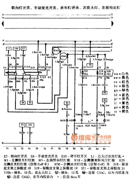
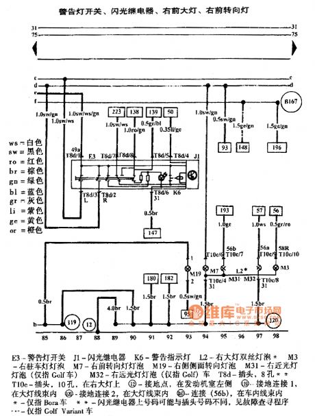
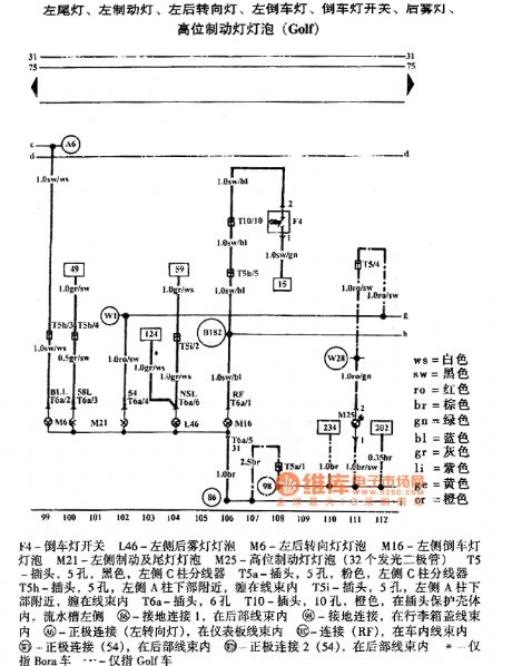
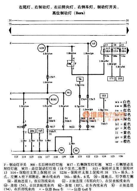
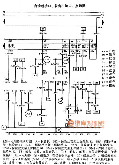
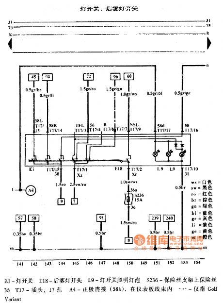
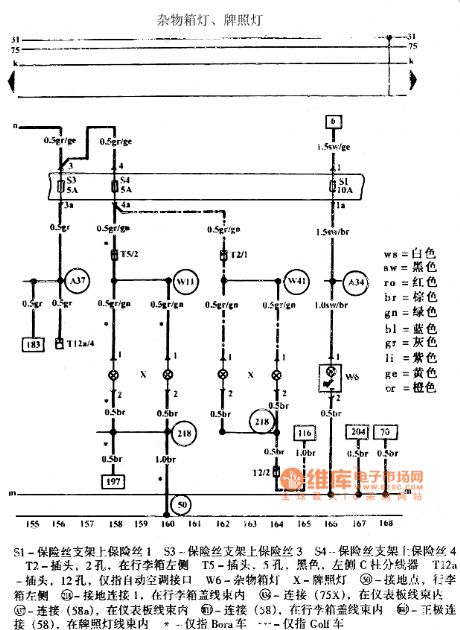
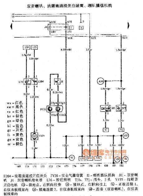
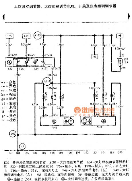
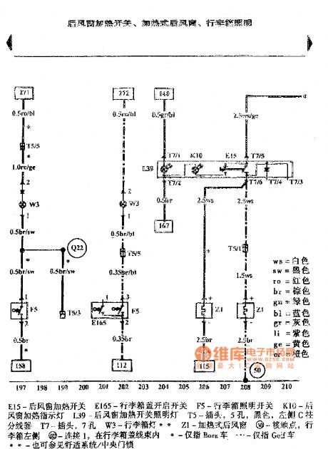
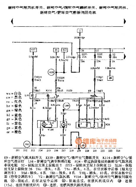
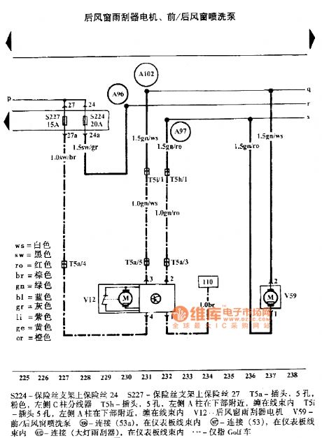
These pictures show the Golf Bora car light circuits.
The picture 1 shows the turning lamp switch, manual dimmer switch, parking lamp switch, left head lamp, left head turning lamp.
The picture 2 shows the warning lamp switch, flash relay, right head lamp, right head turning lamp.
The picture 3 shows the left rear lamp, left brake lamp, left rear turning lamp, left reversing light, reversing light switch, rear fog lamp, high brake lamp bulb (Golf).
The picture 4 shows the right rear lamp, right brake lamp, right rear turning lamp, right reversing light, brake lamp switch, high brake lamp (Bora).
The picture 5 shows the self-diagnostic interface, radio interface, cigarette lighter.
The picture 6 shows the lamp switch, rear fog lamp switch.
The picture 7 shows the sundries box lamp, license plate lamp.
The picture 8 shows the dual-tone horn, fuel tank lid remote-control opening device, horn operating mechanism.
And so on. (View)
View full Circuit Diagram | Comments | Reading(554)
JD-6 Type Electric Motor Synthesized Protector Principle And Troubleshooting Circuit
Published:2011/7/25 8:00:00 Author:Robert | Keyword: Electric Motor, Synthesized, Protector, Principle, Troubleshooting

The JD-6 type electric motor synthesized protector's electrical principle schematic is shown in picture 1 and the assorted wiring with the electric motor is shown in picture 2. In picture 1 the transformer T's secondary side's 15V voltage would be send to the diodes bridge rectifier (D1~D4) and the capacitor C1 for filter. Then it would get about 15V DC voltage which would be the working voltage for the protector. The dual-time-base circuit (NE556) is the main control chip. When the motor is running the current transformer 1TA and 3TA, which are in series with the electric motor's main loop circuit, would be used to detect the motor's running current. After the half-wave rectifier in D5 and filter in C2 and currrnt limiting in R1, the 1TA's secondary side's current signal would make the triode V1 in open mode. As the same way the 2TA, 3TA's current signal would make the triode V2 and V3 in open mode separately. (View)
View full Circuit Diagram | Comments | Reading(3190)
The switch power supply high voltage constant current source circuit (1)
Published:2011/7/21 1:06:00 Author:Borg | Keyword: switch power supply, high voltage, constant current source
Researching instruments need a constant current source which can generate a 1MA current on the 0-3MΩ, and one is designed with UC3845 and 12V battery, the transformer is the color TV high voltage package, of which the L1 is winded for 24 turns with covered wire on the magnet core, L3 is a coil with the former high voltage package, L2 is the high voltage part of the high voltage package. L3 and LM393 compose the voltage limiting circuit, which limits the output current, by adjusting R10, the output voltage of the open circuit can be regulated. (View)
View full Circuit Diagram | Comments | Reading(536)
The constant current source of computing amplifier and Darlington transistor
Published:2011/7/21 0:56:00 Author:Borg | Keyword: computing amplifier, Darlington transistor

As the circuit is fixed with the Darlington tube BSY86, so the output current is high. The max output current value is limited by the resistor of R=150Ω, the output current is regulated by the potentiometer Rp1, and the current is irrelevant to the loading resistor RL but remains as a constant. In the figure, the potentiometer Rp1 is 10kΩ, the current can be regulated in the range of 5μA~40mA. (View)
View full Circuit Diagram | Comments | Reading(914)
| Pages:1467/2234 At 2014611462146314641465146614671468146914701471147214731474147514761477147814791480Under 20 |
Circuit Categories
power supply circuit
Amplifier Circuit
Basic Circuit
LED and Light Circuit
Sensor Circuit
Signal Processing
Electrical Equipment Circuit
Control Circuit
Remote Control Circuit
A/D-D/A Converter Circuit
Audio Circuit
Measuring and Test Circuit
Communication Circuit
Computer-Related Circuit
555 Circuit
Automotive Circuit
Repairing Circuit