
Circuit Diagram
Index 1471
MOSFET gate driver circuit
Published:2011/7/19 8:47:00 Author:Fiona | Keyword: MOSFET gate, driver

MOSFET driver circuit adds a regulator VD1 (UDRM = 8.3V) in the gate and gives the regulator a constant driving voltage,it can ensure MOOSFET always have a very good conduction. MOSEFT machine drive current is controlled by the Rg1 and Rg2,they can reduce the noise through controlling the MOSFET switching speed.When the MOSFET is off, the gate can be discharged through the resistor Rg1 to make the MOSFET quickly close and get the minimum switching loss,it is shown as above.
(View)
View full Circuit Diagram | Comments | Reading(1308)
Electron tube QUADll amplifier circuit diagram
Published:2011/7/25 22:11:00 Author:Ecco | Keyword: Electron tube amplifier

View full Circuit Diagram | Comments | Reading(661)
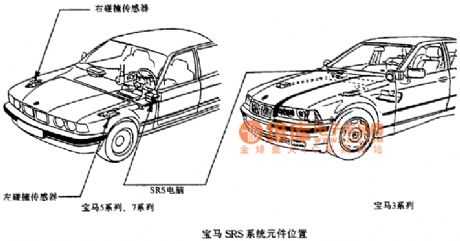
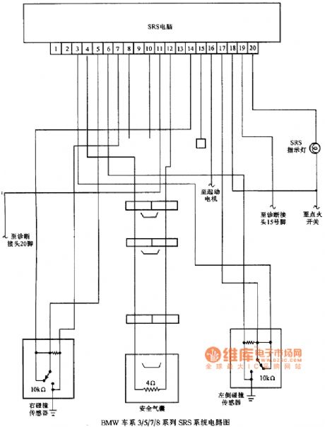
BMW SRS component location circuit diagram
Published:2011/7/26 3:12:00 Author:Ecco | Keyword: BMW , SRS component location
View full Circuit Diagram | Comments | Reading(459)
Nokia 6110 circuit diagram 01
Published:2011/7/26 3:14:00 Author:Ecco | Keyword: Nokia

View full Circuit Diagram | Comments | Reading(791)
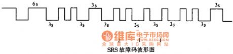
BMW trouble code waveform circuit diagram
Published:2011/7/26 3:16:00 Author:Ecco | Keyword: BMW , trouble code waveform
View full Circuit Diagram | Comments | Reading(484)
BMW Fault code display process circuit diagram
Published:2011/7/26 3:15:00 Author:Ecco | Keyword: BMW , Fault code, display process
View full Circuit Diagram | Comments | Reading(584)
Nokia 6110 circuit diagram 02
Published:2011/7/26 3:14:00 Author:Ecco | Keyword: Nokia

View full Circuit Diagram | Comments | Reading(908)
Scale cleaner
Published:2011/7/26 3:11:00 Author:Ecco | Keyword: Scale cleaner

The scale cleaner circuit is composed of the power circuit, timer, multivibrator and control implementation circuit, and it is shown in Figure 3-211. Power supply circuit is composed of the power transformer T, bridge rectifier UR, filter capacitors Cl, C2, three-terminal integrated voltage regulator ICl, current limiting resistor Rl and power indicator LED VLl. The timer is composed of the time-base timer circuit IC IC2, start button S2, resistors R2, R3, capacitor C3, current limiting resistor R4 and LED VL2 and so on. Rl-R8 use the 1/4W or 1/8W carbon film resistors.
(View)
View full Circuit Diagram | Comments | Reading(499)
Electric heating appliance temperature controller 1
Published:2011/7/26 2:40:00 Author:Ecco | Keyword: Electric heating appliance , temperature controller

The electric heating apparatus temperature control circuit is composed of the power supply circuit and temperature detection control circuit, and it is shown in Figure 3-76. Rl selects the 1/2W metal film resistor; R2 and R3 select 1/4W metal film resistors. RP uses the multi-turn potentiometer. RT uses NTC502 negative temperature coefficient thermistor, and the room temperature (25 ℃) resistance is about 5kΩ. Cl uses the polyester capacitor or CBB capacitor with voltage being greater than 400V; C2 select the aluminum electrolytic capacitor with voltage in 16V. VDl, VD2 choose the 1N4007 silicon rectifier diode.
(View)
View full Circuit Diagram | Comments | Reading(578)
Electric heating appliance temperature controller 2
Published:2011/7/26 2:42:00 Author:Ecco | Keyword: Electric heating appliance, temperature controller

The electric heating apparatus temperature controller circuit is composed of the power supply circuit and temperature detection control circuit, and it is shown in Figure 3-77. Power supply circuit is composed of the power switch S, fuse FU, power transformer T, rectifier diodes VDl-VM, filter capacitor C, three-terminal voltage regulator integrated circuit ICl, current limiting resistor Rl and the power indicator LED VLl. Temperature detection control circuit is composed of the temperature sensing diode VD5, potentiometer RP, electronic switch integrated circuit IC2, relay K, diode VD6, resistor, saturated light-emitting diode VL2.
(View)
View full Circuit Diagram | Comments | Reading(491)
Electric heating appliance temperature controller 4
Published:2011/7/26 2:48:00 Author:Ecco | Keyword: Electric heating appliance , temperature controller

The electric heating apparatus temperature controller circuit is composed of the power supply circuit and temperature detection control circuit, and it is shown in Figure 3-79. Power supply circuit is composed of the power transformer T, bridge rectifier UR, filter capacitors Cl, C2, and three-terminal voltage regulator integrated circuit ICl. Temperature measurement control circuit consists of seven-segment LED digital integrated circuit IC2 and electric hot thermometers Ql-Q7, relays Kl-K7. Cl and C2 select the aluminum electrolytic capacitors with voltage in 25V.
(View)
View full Circuit Diagram | Comments | Reading(517)
Electric heating appliance temperature controller 3
Published:2011/7/26 2:45:00 Author:Ecco | Keyword: Electric heating appliance, temperature controller

The electric heating apparatus temperature controller circuit is composed of the power supply circuit and temperature detection control circuit, and it is shown in Figure 3-78. Power supply circuit is composed of the power transformer T, rectifier diodes VD1-VD4, resistor B1, power indicator LED VL1, filter capacitor C1 and Zener VS. Temperature detection control circuit consists of thermistor RT, time-base integrated circuit IC, potentiometers RPl, RP2, resistors R2, R4, capacitors C2-C4, relay K1, diode VD5 and light-emitting diode VL2.
(View)
View full Circuit Diagram | Comments | Reading(568)
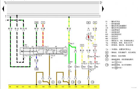
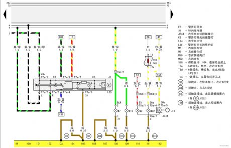
Turning relay warning light switch, right front lamp of Passat GSi circuit diagram 2
Published:2011/7/25 22:01:00 Author:Ecco | Keyword: turning relay , warning light switch, right front lamp , Passat GSi
View full Circuit Diagram | Comments | Reading(539)
Turning relay warning light switch, right front lamp of Passat GSi circuit diagram 1
Published:2011/7/25 22:02:00 Author:Ecco | Keyword: Turning relay , warning light switch, right front lamp , Passat GSi
View full Circuit Diagram | Comments | Reading(498)
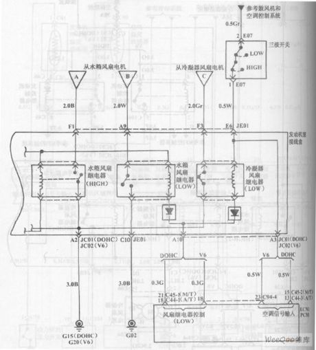
Hyundai Sonata car cooling system circuit diagram 2
Published:2011/7/25 22:09:00 Author:Ecco | Keyword: Hyundai Sonata car , cooling system
View full Circuit Diagram | Comments | Reading(738)
VFC100 synchronizing voltage / frequency converter circuit
Published:2011/7/26 6:28:00 Author:Fiona | Keyword: synchronizing voltage / frequency, converter

VFC100 is asynchronizing voltage / frequency converter which has strong function and it uses charge balance technology.Strict reset combined cycle is from the external clock frequency,it can better eliminate errors and the external timing components' drifting required by other converters. It also uses high-precision input resistor to set full scale input voltage,in many applications,it can obtain the required accuracy without external adjustment.Its typical application circuit is shown as above.
(View)
View full Circuit Diagram | Comments | Reading(622)
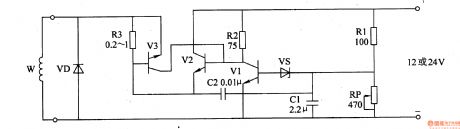
Voltage Regulator (the 3rd)
Published:2011/7/16 0:37:00 Author:Felicity | Keyword: Voltage Regulator
Work of the circuit
The circuit consists of automatic voltage regulation circuit and over-current protection circuit. (It is showed in picture 7-143.)
Automatic voltage regulation circuit consists of Resistors R2, R3, potentiometer RP, capacitor Cl, C2 and Zener diode VS.
Over-current protection circuit consists of Diode VD, resistor R3 and transistor V3.
When the charging voltage of AC electric generator is less than the least value, VS and V1 is cut-off. The charging voltage of AC electric generator is increasing. Here the voltage charges the battery under the certain voltage. When the exporting voltage reaches the highest value, VS is transmitted. The exporting voltage of the motor is decreasing. When the voltage reaches the lowest value, the voltage begins to increase again. In this way, the exporting voltage of the motor is in the scope of 14-14.5 V.
When the working current of V2 is regular, V3 is cut-off. Change the value of RP to change the scope of regulation.
. (View)
View full Circuit Diagram | Comments | Reading(413)
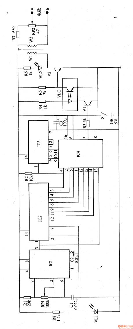
Electrical Pulse Therapeutic Apparatus (the 10th)
Published:2011/7/16 0:39:00 Author:Felicity | Keyword: Electrical Pulse, Therapeutic Apparatus
Work of the circuit
The circuit consists of power circuits, low-frequency oscillator, frequency control circuit and pulse voltage generating circuit. (It is showed in the picture 9-10.)
Power circuit consists of Power switch S, batteries GB, filter capacitor C3, limiting resistor R8 and the power indicator LED VLl.
Low-frequency oscillator consists of Resistors Rl, potentiometers RPl, capacitor Cl, C2 and time-base integrated circuit ICl.
Frequency control circuit consists of count divider integrated circuit IC2, 1C3, electronic switch integrated circuit IC4, resistors R3, R4, transistors Vl and optocoupler light emitting diode inside the VLC.
Pulse voltage generating circuit consists of resistors R5-R7, light-emitting diodes VL2, transistor V2, VLC internal photosensitive transistor, the pulse transformer T, and electrode potential R and poles a, b. (View)
View full Circuit Diagram | Comments | Reading(456)
Electrical Pulse Therapeutic Apparatus (the 6th)
Published:2011/7/16 0:38:00 Author:Felicity | Keyword: Electrical Pulse, Therapeutic Apparatus
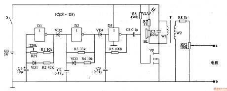
Work of the circuit
The circuit consists of oscillator A-C and pulse voltage generating circuit. (It is showed in the picture 9-6.)
Oscillator A consists of NAND gate IC IC (Dl-D3) within the non-door Dl, resistor RI, R2, diode VDl, capacitors Cl and potentiometer RPl.
Oscillator B consists of C-NOT gate within the D2, resistor R3, R4, capacitor C2 and diode VD4.
Oscillator C consists of lC internal NAND gate D3, resistor R5 and capacitor C3.
Pulse voltage generating circuit consists of Capacitors C4, C5, resistors R6-R8, light-emitting diode VL, field effect transistors VF, the pulse transformer T, potentiometers RP2 and electrodes a, b.
(View)
View full Circuit Diagram | Comments | Reading(432)
Electrical Pulse Therapeutic Apparatus (the 5th)
Published:2011/7/16 0:38:00 Author:Felicity | Keyword: Electrical Pulse, Therapeutic Apparatus
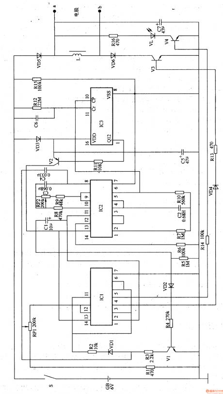
Work of the circuit
The circuit consists of self-excited oscillator, power-delay circuit, low frequency pulse voltage generator and timing control circuit. (It is showed in the picture 9-5.)
Self-excited oscillator consists of IC lC2 pin 8-11 internal circuit and the resistors R8, R9, potentiometer RP2, capacitor C3.
Power-delay circuit consists of IC2 pin 12 and 13 internal circuit and the capacitor Cl, resistors full-R6, transistor Vl, diodes VDl, VD2.
Low frequency pulse voltage generator consists of IC lC1, non-gate integrated circuits IC2, transistor V3, V4, diode VD4-VD6, inductor L, resistor R13-R16, potentiometer RPl, light-emitting diodes and capacitors C7 VL.
Timing control circuit consists of counter integrated circuit IC3, 1C2 1-6 feet in circuit, transistor V2, resistors R7, RlO-Rl2, capacitor C2, C5, C6, and diode VD3. (View)
View full Circuit Diagram | Comments | Reading(428)
| Pages:1471/2234 At 2014611462146314641465146614671468146914701471147214731474147514761477147814791480Under 20 |
Circuit Categories
power supply circuit
Amplifier Circuit
Basic Circuit
LED and Light Circuit
Sensor Circuit
Signal Processing
Electrical Equipment Circuit
Control Circuit
Remote Control Circuit
A/D-D/A Converter Circuit
Audio Circuit
Measuring and Test Circuit
Communication Circuit
Computer-Related Circuit
555 Circuit
Automotive Circuit
Repairing Circuit