
Circuit Diagram
Index 1465
15V,-6V double lines regulated power supply circuit
Published:2011/7/20 0:41:00 Author:Fiona | Keyword: double lines, regulated power supply

15V,-6V double lines regulated power supply circuit is shown as above:
(View)
View full Circuit Diagram | Comments | Reading(661)
Five flash lamp string circuit (4)
Published:2011/7/5 21:54:00 Author:zj | Keyword: Five flash, lamp string circuit

In the graph, SSR1 to SSR5 use TAC081 IC type solid state relay. T uses 220V / 6V, 5VA small quality requirements of power transformers. Itrequires power fora long time without heating. (View)
View full Circuit Diagram | Comments | Reading(659)
Five flash lamp string circuit (3)(Y977A)
Published:2011/7/5 21:59:00 Author:zj | Keyword: Five flash, lamp string circuit

As thecircuit shown in the figure , VTH1 ~ VTH5can useMAC94A4 type small plastic bidirectional thyristor. The maximum drive currentis 1A. (View)
View full Circuit Diagram | Comments | Reading(564)
Five flash lamp string circuit(2)(M1512P)
Published:2011/7/5 22:00:00 Author:zj | Keyword: Five flash, lamp string circuit

View full Circuit Diagram | Comments | Reading(496)
The time-base circuit AC light regulating lamp circuit
Published:2011/7/5 22:15:00 Author:zj | Keyword: The time-base circuit, AC light regulating lamp circuit

View full Circuit Diagram | Comments | Reading(616)
Ten flash lamp string circuit
Published:2011/7/5 22:22:00 Author:zj | Keyword: Ten flash, lamp string circuit

As shown in the figure itis composed of a digital integrated circuit CD4017 consisting of ten flash lamp string controller. VT1 ~ VT10use MCR100-8 type small outline of a unidirectional thyristor. (View)
View full Circuit Diagram | Comments | Reading(1120)
Light control delay lamp circuit (2)
Published:2011/7/4 22:40:00 Author:zj | Keyword: Light control, delay lamp
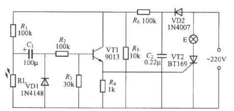
As the diagram shows, it can be used as bedside wall lamp circuit. When you turn off the light to go to bed at night, it can lights up for about 1 minute. It can bring coziness to the bedroom andconvenience to life. This circuit is mainly used for auxiliary lightingafter lights out. Light E should use 5~15W low power lamp. (View)
View full Circuit Diagram | Comments | Reading(710)
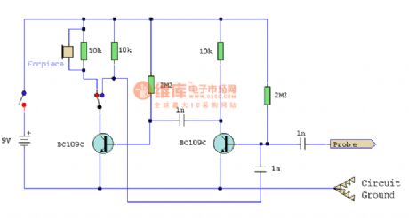
Signal tracing device
Published:2011/7/14 22:26:00 Author:zj | Keyword: Signal tracing
View full Circuit Diagram | Comments | Reading(483)
Digital photoelectric counter(CD4518、CD4543)
Published:2011/7/14 22:39:00 Author:zj | Keyword: Digital, photoelectric counter

The digital electronic counter has intuitive and accurate counting features. It is currently used in a variety industries. The digital electronic counter hasmany counting trigger mode. It is decided bythe actual conditions of use and environment.It can use a mechanical contact type trigger mode, or use electronic sensor's non-contact trigger.A photoelectric sensor is one of them. It is a non-contact electronic sensor.
(View)
View full Circuit Diagram | Comments | Reading(3138)
Arbitrary pulse selection circuit diagram 2(CD40178、CD40106B)
Published:2011/7/14 22:51:00 Author:zj | Keyword: Arbitrary pulse, selection circuit diagram

As shown in the diagram, the circuit structure is simple.The arbitrary pulse selection circuit can alsopreset the number of selected pulsesdirectly using decimalmethod.It is very convenient.
(View)
View full Circuit Diagram | Comments | Reading(850)
Single pulse generating circuit
Published:2011/7/19 21:54:00 Author:zj | Keyword: Single pulse
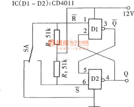
Single pulse could be obtained by a button switch, but due to the button pressing process is easy to produce the chattering phenomenon, and thus which acquired is often not a single pulse, but a group of variable number of pulse series, although some circuits with anti jitter circuit, but for some circuits still can not guarantee its reliability. As shown in the figure the circuit can ensure that each time a button is pressed, you can obtain a pulse, the work is reliable.
(View)
View full Circuit Diagram | Comments | Reading(583)
1 to 9 pulses select circuit (CD4017)
Published:2011/7/19 22:13:00 Author:zj | Keyword: 1 to 9 pulses select
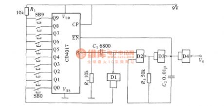
If we want a select multiple pulse, we can adopt the following circuit. You can arbitrarily select pulse in the 1 to 9 range by pressing a button. Its circuit is shown in figure.
(View)
View full Circuit Diagram | Comments | Reading(641)
voltage control oscillator circuit composed of LH0042
Published:2011/7/18 22:31:00 Author:zj | Keyword: voltage control, oscillator circuit

This diagram is voltage controlled oscillator circuit composed of LH0042. In the circuit, A1 is a voltage follower and inverter converter circuit. It provides an integrator equal in absolute values, opposite polarity voltage for A2; A2 is common integrator circuit; A3 exerts a positive feedback, with a comparator and a trigger role; VT1 can be used to do simulation switch, selecting 2SK68 FET, the on-resistance RON is about 100 ohms, and compared to the 47k ohm resistance which is connected with A1 input end, the error is about 0. 2%.
(View)
View full Circuit Diagram | Comments | Reading(1065)
Frequency shift demodulator(748)composed of active power filter
Published:2011/7/18 22:44:00 Author:zj | Keyword: Frequency shift demodulator, active power filter
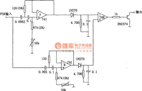
As shown in the figure it is frequency shift demodulator composed of active power filter. Using active power filter instead of LC tuning circuit can makes the frequency shift keying demodulator avoid the use of large and expensive inductors. It not only has the advantagesof small volume, but also improves the performance of demodulation device. The circuit is used for demodulating the 110 bit frequency shift keying signal. Its symbol frequency is 2225Hz. Space frequency is 2025Hz. (View)
View full Circuit Diagram | Comments | Reading(424)
Digital power factor meter composed of ICL7107
Published:2011/7/18 22:48:00 Author:zj | Keyword: Digital, power factor meter

View full Circuit Diagram | Comments | Reading(6432)
ADC1210/1211 12 bit A/D converter
Published:2011/7/17 20:57:00 Author:zj | Keyword: 12 bit, A/D converter

ADC1210/1211 is low power, medium speed 12 bit successive approximation type CMOS package A/D converter. The reference voltage is supplied by external power supply. It can work with single or dual power. Analog input can be monopole or bipolar. Analog input impedanceis 200K ohm. The internal circuit diagram is as shown in the figure. (View)
View full Circuit Diagram | Comments | Reading(723)
Voltage control oscillator circuit composed of μA709
Published:2011/7/17 21:11:00 Author:zj | Keyword: Voltage control, oscillator circuit
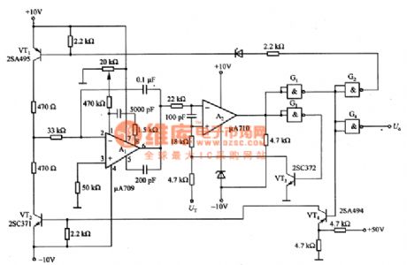
This circuitis a voltage control oscillator circuit composed of μA709. In a circuit,VT1 and VT2can consist of the driving switch circuit;A1 can form Miller integral circuit ; A2 and G1 ~ G3 can constitute a backlash adjustable level comparator circuit. The output of the A2 through the G3 and VT3 are fed to the non-inverting input end to form a positive feedback loop, which constitutes a bistable characteristics of hysteresis comparator circuit.
(View)
View full Circuit Diagram | Comments | Reading(1436)
Photoelectric coupling type TV remote shutdown circuit diagram
Published:2011/7/17 21:51:00 Author:zj | Keyword: Photoelectric coupling type, TV remote shutdown

Photoelectric coupling type TV remote control and shutdown circuitis shown in the diagram. 12V powerin the circuitisfrom the control switching power supply controlledby remote control circuit in the machineor +12V voltage output terminal produced by line circuit. After starting up, + 12V voltage chargeto C1 through the VD1.Optical coupler internal light emitting diodes is cut-off state, so the thyristor is not conductive. The power switch is self-locking and TV works normally.
(View)
View full Circuit Diagram | Comments | Reading(1527)
The water level detection circuit
Published:2011/7/12 3:58:00 Author:zj | Keyword: The water level, detection circuit

View full Circuit Diagram | Comments | Reading(732)
The oscillation circuit with automatic gain control (AGC)
Published:2011/7/17 22:06:00 Author:zj | Keyword: oscillation circuit, automatic gain control

Thediagram is the oscillation circuit with automatic gain control ( AGC). In the circuit, A1 ~ A3 is circuits whichchangeAC signal from the pickup output into a DC signal. The DC signal changes can be used as a comparator A4 input signal, which is then compared with a reference voltage. It does the oscillator output amplitude modulation. Due to the A3 output DC signal fluctuation components, it will affect the normal work of the comparator A4.
(View)
View full Circuit Diagram | Comments | Reading(1083)
| Pages:1465/2234 At 2014611462146314641465146614671468146914701471147214731474147514761477147814791480Under 20 |
Circuit Categories
power supply circuit
Amplifier Circuit
Basic Circuit
LED and Light Circuit
Sensor Circuit
Signal Processing
Electrical Equipment Circuit
Control Circuit
Remote Control Circuit
A/D-D/A Converter Circuit
Audio Circuit
Measuring and Test Circuit
Communication Circuit
Computer-Related Circuit
555 Circuit
Automotive Circuit
Repairing Circuit