
Circuit Diagram
Index 1462
The seeder channel block alarm (2)
Published:2011/7/23 22:05:00 Author:qqtang | Keyword: seeder channel, block alarm

The working principle of the circuitThe seeder channel block alarm circuit consists of the photoelectric control circuit, single steady circuit, 1HZ multi-resonance oscillator, 1KHZ multi-resonance oscillator phase indicator circuit, see as figure 4-104.
The photoelectric control circuit consists of the indicators HL1 and HL3, transistors V2 and V3, resistors R6-R11, capacitors C8-C11, diode VD1 and reset key S1.The astable circuit consists of the potentiometer RP1, capacitors C1 and C2, time-base integrated circuit IC1. (View)
View full Circuit Diagram | Comments | Reading(481)
The bicycle night flashing tail lamp
Published:2011/7/23 21:57:00 Author:qqtang | Keyword: tail lamp, bicycle

The working principle of the circuit The bicycle night flashing tail lamp circuit consists of light control circuit, trigger control circuit, astable multi-resonance oscillator and LED flashing circuit, see as figure 7-37.
The light control circuit consists of the light sensitive transistor V, capacitor C1, resistor R2 and 4-pin internal circuit of the time-based integrated circuit IC.The trigger control circuit consists of the trigger switch S, resistors R1 and R2 and capacitor C1. (View)
View full Circuit Diagram | Comments | Reading(1510)
The fuse box indicator (1)
Published:2011/7/23 21:45:00 Author:qqtang | Keyword: fuse box, indicator

Here is to introduce a fuse box indicator composed of the CMOS digital integrated circuit and double color LED VL, which can monitor the fuse box working state in the car. When the fuse box is normal, VL is glowing green light; when the fuse box is broken down, VL is glowing red light.The working principle of the circuitThe fuse box indicator circuit consists of resistors R1-R9, NOR gate integrated circuit IC(Dl-D6) and double color LED VL1-VL3, see as figure 7-44.
(View)
View full Circuit Diagram | Comments | Reading(736)
The computer mainboard circuit 830_41
Published:2011/7/20 8:12:00 Author:qqtang | Keyword: computer mainboard
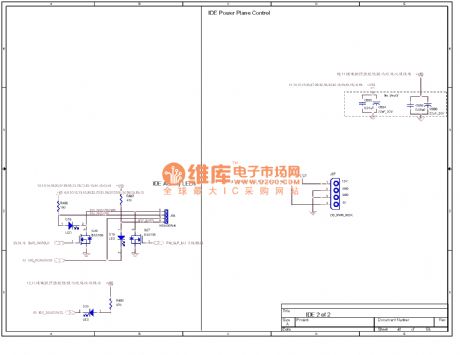
View full Circuit Diagram | Comments | Reading(407)
Light control road lamp automatic control circuit
Published:2011/7/14 23:14:00 Author:Fiona | Keyword: Light control road lamp, automatic control

Connected to 220v AC power,the both ends of capacitor C4 will obtain ten 12v DC.At night,photoresistance RG is a high resistance,transistor VTl, v1,v2 are closed.The relay KMl has no power,the contacts 2-3 of KMl are closed.AC relay KM2 works with power.The contacts l-2 ,4-5 of KM2 are closed, light-emitting diode vD3 displays $signal instructions,floodlight H automatically kindle.At dawn,RG is a low resistance,VT1 conducts when it obtains base current,the radiation high potential output makes vT2 saturated conductivity. (View)
View full Circuit Diagram | Comments | Reading(787)
The circuit of counter composed of digital circuit
Published:2011/7/14 23:12:00 Author:Fiona | Keyword: counter, digital circuit


The digital circuit composed of counter as shown in figure uses infrared ray as the detection signals,a small device for scanning count moving target is applicable to the production line, it can count fast and accurate the moving items on the conveyor belt. It can also be used for other purpose, such as counting the passagers of enterance or exit and so on. The circuit’s characteristic is the simple structure, making easy, economical and practical. There is also a most prominent advantage that it can count the different shading number of items directly.
(View)
View full Circuit Diagram | Comments | Reading(561)
More precise constant voltage and constant current circuit composed of output voltage sag compensation function
Published:2011/7/20 0:41:00 Author:Fiona | Keyword: sag compensation function, constant voltage, constant current
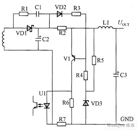
The current mode working state:constant current control mode compares with the voltage drop of current sampling resistor R7 through setting the optocoupler LED's voltage drop.When the output current is not up to the constant current set point,the voltage drop of R7 reduces and it can be ignored;when the output current reaches the constant current point, C3 voltage drop of R7 increases,this increasing voltage converts the voltage into current and adds to the optocoupler's LED through the resistor R6 to make the current flowing through the LED increase, through the circuit's feedback GND control function,the output current is constant.
(View)
View full Circuit Diagram | Comments | Reading(514)
headphone amplifier composed of ECC822 tube circuit
Published:2011/7/14 23:12:00 Author:Fiona | Keyword: headphone amplifier, tube

Pre-amplifier should generate sufficient signal amplitude to drive the headphones. The transistor part of pin 1,2,3 amplifies the signal. Input signal through the 50kΩ volume control logarithmic potentiometer P1 (P1 is not in Figure I) reaches the circuit board, and then inputs to the pre-amplifier stage directly through C1 and R1, and R1 and C1l provide the necessary negative gate bias. Gain is essentially determined by the R8. The maximum input voltage is determined by R2. R9 is so determined. That the current of the static anode chooses in the linear part of characteristic curve as possible.
(View)
View full Circuit Diagram | Comments | Reading(951)
the smart battery charger circuit that using a single transistor
Published:2011/7/14 23:09:00 Author:Fiona | Keyword: the smart battery charger, using a single transistor

circuit work
First, the variable voltage power supply is fixed at 13.3 V dc - This is battery electricity voltage,and is connected to the battery's connection point of this circuit.The slider of VR1 is transferred to the top of the battery positive electrode. The slider of VR2 should be adjusted to one end connecting VR1. The transistor starts to work to shunt VR1. Then,the slider of VR1 is adjusted to the other side, that is one end of connecting VR2.
Now,let the test voltage is 11.8 V dc, which is the voltage when the battery runs out. Then, adjust VR2 so that the transistor no longer work. Test voltage is further increased to 13.3 V dc, adjust VR1 to make transistors work. By setting the upper and lower voltage, NC point is connected to the circuit. A battery charger is ready now.
(View)
View full Circuit Diagram | Comments | Reading(825)
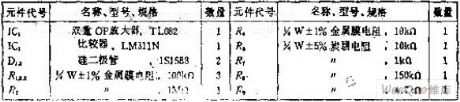
The zero differential coefficient peak time detection circuit
Published:2011/7/14 23:07:00 Author:Fiona | Keyword: zero differential coefficient, peak time detection circuit
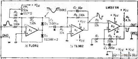
Circuit Work
Circuit slightly is offset. Remove the noise of the input signal to make the circuit to avoid the error action.OP amplifier A1 is the ideal half-wave detector circuit.It outputs reverse signal, this signal is added to the differential circuit A2, and do the differential, and then seeks the zero-crossing time.Doing the zero-cross detection with comparator A3, the rising edge of the output pulse is the peak time. If the input waveformisthe same, there is nothing with its magnitude, only do zero-cross detection of the differential coefficient. Differential capacitor is 0.001UF, the input signal frequency range is about 100HZ ~ 10KHZ, if the input signal frequency is outside of this range, C1's capacity should be changed accordingly. (View)
View full Circuit Diagram | Comments | Reading(555)
The 2.5L(LBB) and 3.0L(LW9) engine circuit of Shanghai GM Buick-Regal(9)
Published:2011/7/20 2:19:00 Author:Borg | Keyword: engine circuit, Buick-Regal
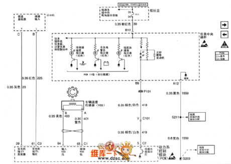
Figure 1. The 2.5L(LBB) and 3.0L(LW9) engine circuit of Shanghai GM Buick-Regal (9) (View)
View full Circuit Diagram | Comments | Reading(375)
The 2.5L engine transmission gear switch circuit of Shanghai GM Buick-MPV (GL8)
Published:2011/7/20 2:53:00 Author:Borg | Keyword: transmission, gear switch
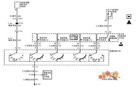
The 2.5L engine transmission gear switch circuit of Shanghai GM Buick-MPV (GL8)
(View)
View full Circuit Diagram | Comments | Reading(361)
The 2.5L(LBB) and 3.0L(LW9) engine circuit of Shanghai GM Buick-Regal (10)
Published:2011/7/20 2:16:00 Author:Borg | Keyword: engine circuit, Buick-Regal
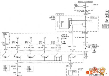
Figure 1. The 2.5L(LBB) and 3.0L(LW9) engine circuit of Shanghai GM Buick-Regal (10) (View)
View full Circuit Diagram | Comments | Reading(372)
The 2.5L(LBB) and 3.0L(LW9) engine circuit of Shanghai GM Buick-Regal (11)
Published:2011/7/20 2:16:00 Author:Borg | Keyword: engine circuit, Buick-Regal
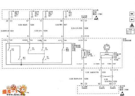
Figure 1. The 2.5L(LBB) and 3.0L(LW9) engine circuit of Shanghai GM Buick-Regal (11) (View)
View full Circuit Diagram | Comments | Reading(344)
The 3.0L engine A/C pressure sensor and admission temperature sensor circuit of Shanghai GM Buick-MPV (GL8)
Published:2011/7/20 2:52:00 Author:Borg | Keyword: A/C pressure sensor, admission temperature sensor
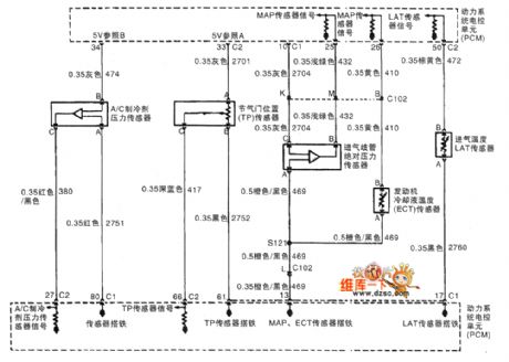
The 3.0L engine A/C pressure sensor, throttle position sensor, admission MAP sensor, auto speeder and admission temperature sensor circuit of Shanghai GM Buick-MPV (GL8)
(View)
View full Circuit Diagram | Comments | Reading(433)
The 3.0L engine emission recycle and power system control unit circuit of Shanghai GM Buick-MPV (GL8)
Published:2011/7/20 2:46:00 Author:Borg | Keyword: emission recycle, power system control unit
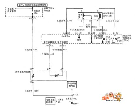
The 3.0L engine oxygen sensor, emission recycle and power system control unit circuit of Shanghai GM Buick-MPV (GL8)
(View)
View full Circuit Diagram | Comments | Reading(410)
The 3.0L engine air flow meter and vapor emission circuit of Shanghai GM Buick-MPV (GL8)
Published:2011/7/20 2:42:00 Author:Borg | Keyword: air flow meter, vapor emission, Buick-MPV
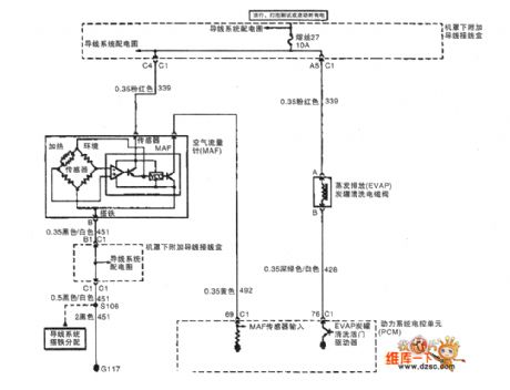
The 3.0L engine air flow meter and vapor emission circuit of Shanghai GM Buick-MPV (GL8)
(View)
View full Circuit Diagram | Comments | Reading(512)
The 3.0L engine oil level switch and oil pressure indicator circuit of Shanghai GM Buick-MPV (GL8)
Published:2011/7/20 2:39:00 Author:Borg | Keyword: oil level switch, oil pressure indicator
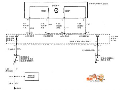
The 3.0L engine idle speed control, oil level switch and oil pressure indicator circuit of Shanghai GM Buick-MPV (GL8)
(View)
View full Circuit Diagram | Comments | Reading(477)
The 3.0L engine generator, dashboard and speed sensor circuit of Shanghai GM Buick-MPV (GL8)
Published:2011/7/20 2:36:00 Author:Borg | Keyword: engine generator, dashboard, speed sensor
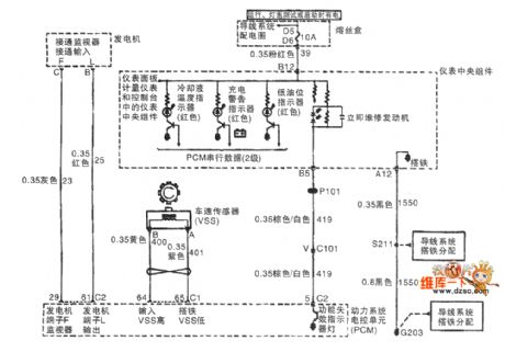
The 3.0L engine generator, dashboard and speed sensor circuit of Shanghai GM Buick-MPV (GL8)
(View)
View full Circuit Diagram | Comments | Reading(432)
The 2.0L(L34) engine, input/output and car speed sensor circuit
Published:2011/7/20 3:35:00 Author:Borg | Keyword: input/output, car speed sensor
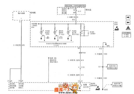
Figure 1. The 2.0L(L34) engine, input/output and car speed sensor circuit of Shanghai GM Buick-Regal
(View)
View full Circuit Diagram | Comments | Reading(1509)
| Pages:1462/2234 At 2014611462146314641465146614671468146914701471147214731474147514761477147814791480Under 20 |
Circuit Categories
power supply circuit
Amplifier Circuit
Basic Circuit
LED and Light Circuit
Sensor Circuit
Signal Processing
Electrical Equipment Circuit
Control Circuit
Remote Control Circuit
A/D-D/A Converter Circuit
Audio Circuit
Measuring and Test Circuit
Communication Circuit
Computer-Related Circuit
555 Circuit
Automotive Circuit
Repairing Circuit