
Circuit Diagram
Index 1468
Golf Bora Instrument Cluster Circuit
Published:2011/7/25 10:17:00 Author:Robert | Keyword: Golf, Bora, Instrument, Cluster
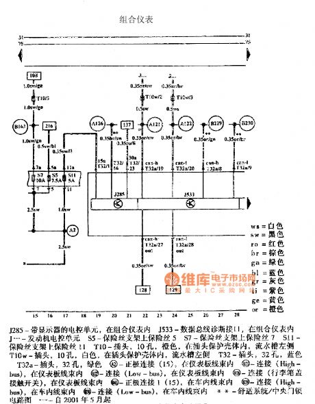
The pictures show the Golf Bora instrument cluster circuits.
The first picture shows the instrument cluster circuit.
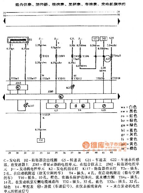
The second picture shows the instrument cluster, anti-theft circuit, tachometer, odometer, speedometer, power generator indicating lamp.
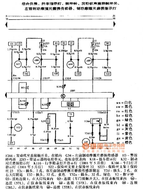
The third picture shows the instrument cluster, trailer indicating lamp, digital clock, engine compartment lid contacting switch, left-front brake friction plate wear sensor, brake friction plate wear indicating lamp.
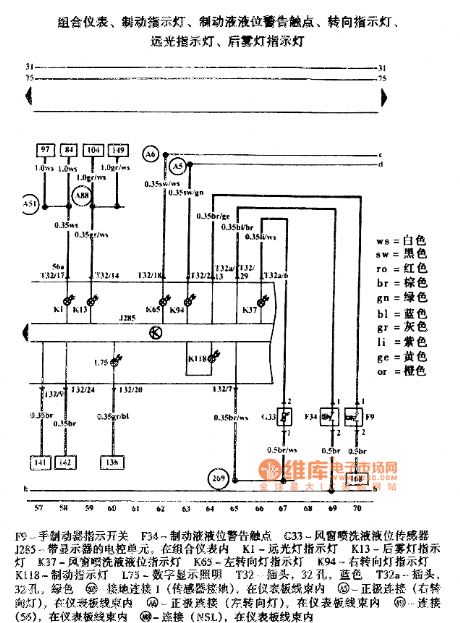
The fourth picture shows the instrument cluster, brake indicating lamp, brake liquid level alarm contactor, turning indicating lamp, high beam indicating lamp, rear fog indicating lamp. (View)
View full Circuit Diagram | Comments | Reading(806)
Golf Bora Automatic Anti-Glare Car Inside Rearview Mirror And Rain Sensor Circuit
Published:2011/7/25 19:54:00 Author:Robert | Keyword: Golf, Bora, Automatic, Anti-Glare, Car, Rearview Mirror, Rain Sensor
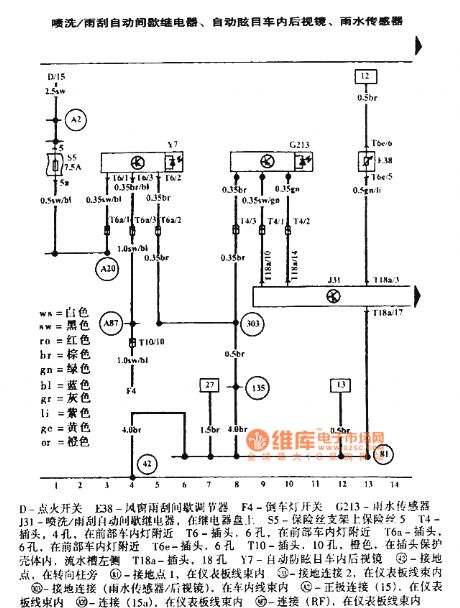
The pictures show the Golf Bora automatic anti-glare car inside rearview mirror and rain sensor circuits.
The first picture shows the spraying/wiper automatic intermittent relay, automatic anti-glare car inside rearview mirror, rain sensor.
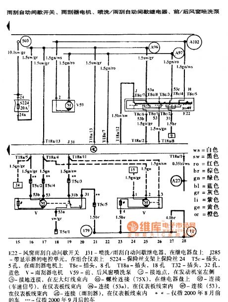
The second picture shows the wiper automatic intermittent switch, wiper electric motor, spraying/wiper automatic intermittent relay, front/rear windshield spray pump.
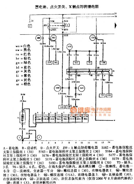
The third picture shows the battery, ignition switch, X contactor unloading relay. (View)
View full Circuit Diagram | Comments | Reading(1413)
The RC control frequency voltage transformer
Published:2011/7/21 0:41:00 Author:Borg | Keyword: voltage transformer, control frequency
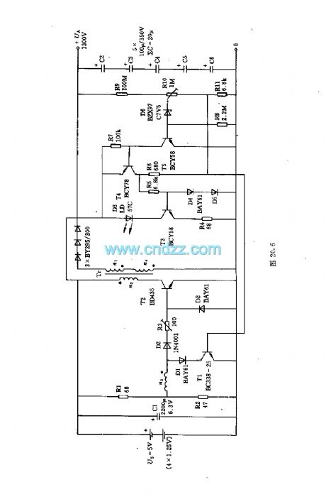
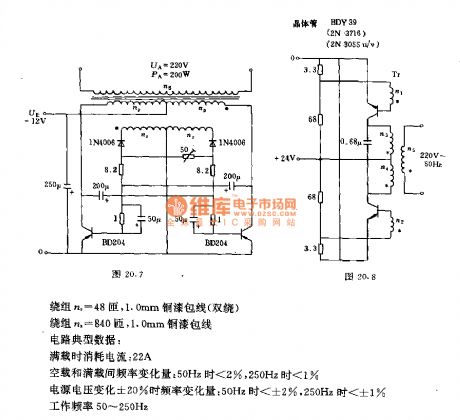
The circuit generates the stable AC voltage with changeable frequency through the multi-resonance oscillator composed of RC circuit, the voltage is output after it is coupled by the transformer. The data of the transformer:
The coil np=40 turns, 2.5mm copper enamelled wire(double turns, internal)
The coil nr=48 turns, 1.0mm copper enamelled wire(double turns)The coil ns=48 turns, 1.0mm copper enamelled wireTypical data of the circuit:The consumed current of full load:22A (View)
View full Circuit Diagram | Comments | Reading(696)
The signal generator of changeable working frequency
Published:2011/7/21 0:30:00 Author:Borg | Keyword: signal generator, working frequency
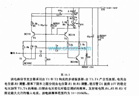
The signal generator consists of the multi-resonance oscillator composed of T1 and T2, the constant current source is generated by T3 and T4. The current is regulated by potentiometer R2, the frequency upper limit and lower limit are regulated by R1 and R3 respectively. The voltage stabilizer D1 provides with a 10V stable voltage for the basic poles of T3 and T4, so the frequency can be regulated when the voltage is changing. The emitter resistors of R4, R5 and R3 can limit the maximum input current. The frequency range of the circuit is about 10~200kHz. (View)
View full Circuit Diagram | Comments | Reading(588)
Golf Bora Telephone Circuit
Published:2011/7/26 7:09:00 Author:Robert | Keyword: Golf, Bora, Telephone
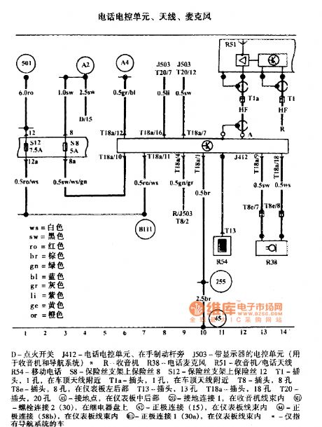
The picture shows the Golf Bora telephone circuit.
The picture shows the telephone electrical control unit, antenna, microphone. The D is ignition switch. The J412 is telephone electrical control unit which is beside the hand brake lever. The J503 is the electrical control unit with monitor (it is used for radio and navigation system). The R is radio. The R38 is telephone micrphone. The R51 is radio/telephone antenna. The R54 is mobile phone. The S8 is the fuse 8 on the fuse holder. The S12 is the fuse 12 on the fuse holder. The T1 is plug with 1 hole which is beside the car roof antenna. The Tla is plug with 1 hole which is beside the car roof antenna. The T8 is plug with 8 holes. The T8e is plug with 8 holes which is in the left-rear dashboard. And so on. (View)
View full Circuit Diagram | Comments | Reading(457)
The food humidity detector circuit (2)
Published:2011/7/21 0:21:00 Author:Borg | Keyword: humidity detector circuit
(View)
View full Circuit Diagram | Comments | Reading(719)
Golf Bora Radio Circuit
Published:2011/7/26 9:54:00 Author:Robert | Keyword: Golf, Bora, Radio
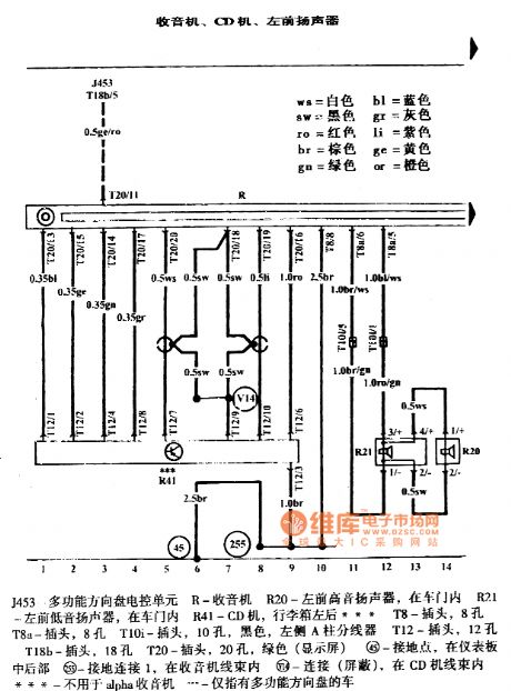
The pictures show the Golf Bora radio circuits.
The first picture shows the radio, CD player, left-front speaker.
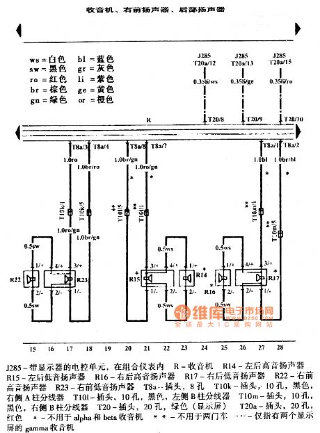
The second picture shows the radio, right-front speaker, rear speaker.
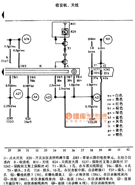
The third picture shows the radio and antenna. In the picture the part D is ignition switch. The E20 is switch and instrument lighting regulator. The J285 is an ECU with monitor inside the instrument cluster. The R is radio. The R11 is antenna. The R24 is antenna amplifier. The S237 is the fuse on the fuse holder 37. The S242 is the fuse on the fuse holder 42. The T1 is a plug with 1 hole near the car roof antenna. The T6c is plug with 6 holes. The T8 is plug with 8 holes. The T16 is plug at the middle of the dashboard with the self-diagnosis interface. The T32 is plug with 32 holes. And so on. (View)
View full Circuit Diagram | Comments | Reading(602)
The food humidity detector circuit (1)
Published:2011/7/21 0:13:00 Author:Borg | Keyword: food humidity detector

Element selectionR1~R3 are adopted with the 1/4 carbon film resistor; R4 is the 1/2W metal film resistor; RP is the mixed film potentiometer; C1 and C2 are the dacron capacitor or the monolith capacitor; C3 and C4 are the high frequency pottery capacitor; C5 is the aluminum electrolytic resistor with the withstand voltage of 16V; VD1 and VD2 are the 2AP9 ordinary Ge diodes or IN4148 silicon switch diodes; VS is the 2CW14 or 2CW55(1/4W, 6~7.5V) regulated diode. (View)
View full Circuit Diagram | Comments | Reading(588)
The bridge voltage transformer
Published:2011/7/21 0:05:00 Author:Borg | Keyword: voltage transformer

The circuit is equal to 2 serial transformers of parallel connection, which works in push-pull way, so the power supply doesn't need to have middle point. The left-upper and right-lower transistors of the transformer are always at the close or open state at the same time, and their states are opposite to the other two transistors. The circuit starts to oscillate with the help of the additional coil, the coil generates the impact current by key T or pulse contactor. The amplitude of the oscillation pulse is limited by the resistor. (View)
View full Circuit Diagram | Comments | Reading(423)
The temperature detection alarm circuit
Published:2011/7/20 23:57:00 Author:Borg | Keyword: alarm circuit
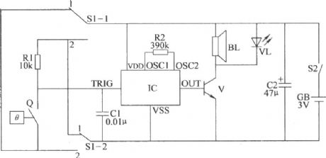
Here is to introduce the temperature detection alarm circuit, which is made of the heat temperature and audio integrated circuit, it characterizes simple and practical circuit, it can not only be used as the over-temperature alarm, but also be the low-temperature alarm.The temperature detection alarm circuit consists of the temperature detection control circuit and acousto-optical alarm circuit, see as the figure.
(View)
View full Circuit Diagram | Comments | Reading(704)
The dual limit temperature alarm circuit (2)
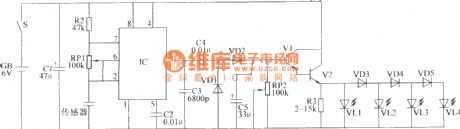
Published:2011/7/20 23:50:00 Author:Borg | Keyword: temperature alarm circuit

Element selectionR1~R16 are selected with the 1/4 metal film resistor or the carbon film resistor; RT is the negative coefficient thermistor; RP1 and RP2 are the small multi-turn potentiometers; C1~C4, C6 and C7 are the aluminum electrolytic resistors of 16V; C5 is the dacron or monolith capacitor; VD1~VD3 are the 1N4148 silicon switches diodes; VL1~VL3 are the high brightness LED of φ3mm, VL1 is yellow, VL2 is red, VL3 is green. (View)
View full Circuit Diagram | Comments | Reading(452)
The SIPMOS control circuit with transformer LEV separator
Published:2011/7/20 23:40:00 Author:Borg | Keyword: control circuit, LEV separator

The T1 in the circuit works as the phaser reversing state, T2 is controlled by R2, and T1 can make it blocked quickly. R1, R5, R2 and R4 are used to prevent from wrongly conducting when the power supply voltage rises, D7 and D8 are used to remove the magnetism of the transformer, R3 is to reduce the oscillation that may happen. The second part of the transformer has almost the same functions with the first stage. The feature of the circuit is that it can simultaneously control more than one SIPMOS transistors. (View)
View full Circuit Diagram | Comments | Reading(441)
The SIPMOS transistor inter-compensation Darlington control circuit
Published:2011/7/20 23:18:00 Author:Borg | Keyword: SIPMOS, transistor, Darlington control circuit

T1 is conducting when the output transistor of TDA4700 is conducting, the emitter current is limited by R3 and T3 is controlled by D3. At the same time, T2 basic pole is positive to the emitter, so T2 is blocked, so is T4. If the output transistor of SIPMOS is blocked, both T1 and T3 are blocked. The input capacitor of SIPMOS transistor is charged by T2 and R4, so T2 controls T4, which accelerates the discharging process. The virtue of the circuit is that the attracted current is low but the controlled current is high. (View)
View full Circuit Diagram | Comments | Reading(534)
The basic knowledge and drive of standard and white light LED
Published:2011/7/20 23:09:00 Author:Borg | Keyword: basic knowledge, white light LED
The simplest way to make the LED work is to connect a resistor serially with it through a voltage source. As long as the working voltage (VB) is stable, LED will shed stable light with constant power (although the power of the light will decrease as the temperature rises). By changing the resistance of the serial resistor, the light power can be adjusted to the value that is needed. For a standard LED whose diameter is 5mm, figure1 represents the function curve of forward conducting voltage(VF) and forward (IF). (View)
View full Circuit Diagram | Comments | Reading(487)
The PFC full attraction main circuit
Published:2011/7/20 22:59:00 Author:Borg | Keyword: PFC, full attraction

The charge process of normal charge modes is often done in homes or public places, and the charge power of normal charge modes is often 6.6KW, the typical charge time is 5~8h. The power converters of the normal charge mode and emergency charge mode are almost the same, the normal charge mode can also be adopted with the AC/DC converter. As the switch tube takes with single stage converter of the PFC function, its peak value is very high.
(View)
View full Circuit Diagram | Comments | Reading(575)
The dual-channel long-line transmission circuit
Published:2011/7/20 22:31:00 Author:Borg | Keyword: dual-channel, long-line transmission


The main feature of the long-line transmission is that the input and output circuits are adopted with the photoelectric separation technology, which fulfills the full electric separation between the computer and communication line, communication line and the terminal equipment. So the accident voltage, electromagnet inductance and disturbance signal are prevent from running into the computer and the terminal equipment, and the reliability and stability of the computer are improved.
(View)
View full Circuit Diagram | Comments | Reading(554)
The KJ004 SCR phase drifting trigger circuit
Published:2011/7/20 22:51:00 Author:Borg | Keyword: phase drifting, trigger circuit


The KJ004 SCR phase drifting trigger circuit is suitable for the single phase, 3-phase bridge power supply devices as the dual-channel pulse phase drifting trigger of SCR. KJ004 outputs two lines of drifting pulses which differ 180⁰, so they can easily compose the full-control bridge trigger line. The circuit characterizes large load, good transposition, good balance of the forward/backward pulse, wide transposition range, low requirement on synchronous voltage, output terminal with pulse modulation and so on.
(View)
View full Circuit Diagram | Comments | Reading(2203)
The dual-channel infrared sound volume remote control circuit
Published:2011/7/20 22:40:00 Author:Borg | Keyword: sound volume, remote control

The dual-channel sound volume remote control uses 4 keys: CHL+(the left sound channel volume increases), CHL-(the left sound channel volume decreases), CHR+(the right sound channel volume increases), CHR-(the right sound channel volume decreases). IC1 is the preamplifier of infrared, the 5mH inductor and 3300pF capacitor compose the filter circuit which outputs the modulation signal from ①, the signal is sent to IC2 for decoding after its phase is reversed by T1.
(View)
View full Circuit Diagram | Comments | Reading(516)
M9900MC Camera Self-Diagnosis Repairing Status Mode Circuit
Published:2011/7/26 1:54:00 Author:Robert | Keyword: Camera, Self-Diagnosis, Repairing, Status, Mode

1.Repairing status mode.When the machine is in the repairing status mode, the TV sets and viewfinders' screen would display the data of the random access memory (RAM). The table 1 lists the RAM data's reading imformation and all the data is in hexadecimal mode for displaying.2.Data details in repairing status mode.When pressing the start/stop switch and the memory switch at the same time, after the power switch is connected, the TV sets' screen could display the detail information of No.1 to No.23 which is listed in table 2. And part of the data number's indicating imformation is listed after the list's contents.
The picture shows the M9900MC camera self-diagnosis repairing status mode circuit. (View)
View full Circuit Diagram | Comments | Reading(1262)
The DC booster circuit fitted in multimeters
Published:2011/7/20 22:23:00 Author:Borg | Keyword: DC booster, multimeters
The multimeter is a necessary tool for the electrician and electric technique worker, whose high impedance gear often uses a laminated cell of 9V, 15A or 22.5A. The cell is not only costly, but also short-lived, so it's not economic to change it often. Here is to introduce some small DC booster circuits which are fitted for the multimeter. These circuits are simple and they have few elements, after conversion, they can be directly installed in the laminated cell position to replace the cell. (View)
View full Circuit Diagram | Comments | Reading(525)
| Pages:1468/2234 At 2014611462146314641465146614671468146914701471147214731474147514761477147814791480Under 20 |
Circuit Categories
power supply circuit
Amplifier Circuit
Basic Circuit
LED and Light Circuit
Sensor Circuit
Signal Processing
Electrical Equipment Circuit
Control Circuit
Remote Control Circuit
A/D-D/A Converter Circuit
Audio Circuit
Measuring and Test Circuit
Communication Circuit
Computer-Related Circuit
555 Circuit
Automotive Circuit
Repairing Circuit