
Circuit Diagram
Index 60
555 LED Flasher
Published:2013/9/4 20:02:00 Author:lynne | Keyword: 555 LED Flasher
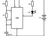
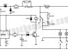
This is a small size led flasher built with the 555 timer IC that is powered from 2 x 1.5V batteries. The circuit can be used as a flashing metronome, dark room timer, memo-reminder or other similar applications.
The IC is connected as a astable multivibrator with a duty cycle of about 10%.In figure 1 the LED will be ON for a short period of time and OFF for a longer period. The duty cycle can be reversed if the LED is connected as shown in figure 2 but the battery consumption will also increase due to the fact that the LED will stay ON for a longer period of time. in figure 3 for a variable flash rate, replace the 220k pot with a 220k in series with a 22k resistor. And that is a simple 555 led flasher circuit. (View)
View full Circuit Diagram | Comments | Reading(1283)
Light Activated Relay with 555 IC
Published:2013/9/4 20:01:00 Author:lynne | Keyword: Light Activated Relay with 555 IC

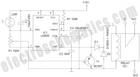
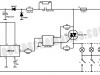
This light activated relay circuit presented here uses the 555 timer IC and a light dependent resistor or LDR to form a light sensitive relay in an intruder alarm system or for switching on a lamp at Sun set and off at Sun rise.
Potentiometer R1 value must be chosen and then adjusted that under normal conditions when the light is falling on the LDR the voltage across the LDR is less than 1/3 of Vcc. The output of the 555 IC is high now. The actual value of R1 will depend on the resistance of the LDR.
When the light fades or is interrupted by an intruder, the voltage across it rises above 2/3 of Vcc, tripping the IC flip-flop. The output goes low activating the relay. When the light is restored, voltage falls below 1/3 of Vcc, again tripping the flip-flop causing the output to go high and the relay drops.
The difference of 1/3 of Vcc between turning on and turning off voltages prevents relay chatter. This differential can be reduced by connecting a resistor R2 shown dotted in the schematic. Its value is about one and a half times of the LDR resistance in its illuminated condition. Use a 6V or 12V relay with a current of 200mA max.
(View)
View full Circuit Diagram | Comments | Reading(1768)
Automatic Bike Headlight Switch
Published:2013/9/4 19:59:00 Author:lynne | Keyword: Automatic Bike Headlight Switch
Improved bike headlight switch circuit presented here has been designed to switch bike headlight on (or similar loads) at a presettable ambient light level. The circuit is based on the renowned timer chip LM555 (IC1), here triggered by a decrement in ambient light level. Here is a 220V automatic light switch, just in case you need one.
Bike Headlight Switch Notes
The whole circuit should be powered from the 12V bike battery
Slight intervention in the existing electrical wiring of the vehicle may become necessary to add this circuit
Use of a medium-size encased LDR is recommended for reliable operation. Fit the LDR at the front side of the bike in an appropriate position
The relay used in the prototype draws near 37.5 mA. 555 IC output can switch up to 100mA, which is adequate for driving the relay
555 IC will only rise to near 10v for the 12V input supply and the diode D1 will drop 0.7Volt. As a result the 12V relay will only get about 9.3Volt. However, pick-up voltage of a standard 12V relay is 9V, this is not a problem. D1 is added intentionally to avoid episodic timer latch up (View)
View full Circuit Diagram | Comments | Reading(1196)
Microcontroller Relay Interface and Driver
Published:2013/9/3 20:14:00 Author:lynne | Keyword: Microcontroller Relay Interface and Driver
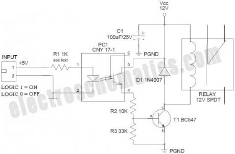
Many microcontroller designs typically mix multiple interfacing methods. A microcontroller (µC) system can be viewed as a system that reads from inputs, performs processing and writes to outputs. Microcontrollers are useful to the extent that they communicate with other devices, such as sensors, motors, switches, keypads, displays, memory and even other micro-controllers. Often a need arise to interface output of the microcontroller with an electromagnetic relay (EMR).
Relays are devices which allow low power circuits to switch a relatively high Current and/or Voltage on/off. Here is a simple microcontroller-relay interface circuit with perfect “galvanic isolation”. “Galvanic isolation”means an isolation between two circuits, i.e. no metal conduction between those circuits. Transfer will then take place for instance optical or by induction. Galvanic means “related to DC”. Galvanic Isolation says that the driver circuit is separated from the signal source in such a way that DC current cannot bridge the connection. The widely accepted method for galvanic isolation is the use of optical isolator (optocoupler/photocoupler).
(View)
View full Circuit Diagram | Comments | Reading(1318)
555 Temperature Controller Circuit
Published:2013/9/3 20:04:00 Author:lynne | Keyword: 555 Temperature Controller Circuit
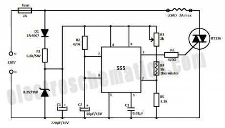
You can build a temperature controller circuit with the 555 IC together with a thermistor resistor divider. The advantage is that a well regulated power supply is not needed. The dividing network consists of adjustable resistor R3, thermistor R4 and R5.
When the thermistor temperature is below a set value the voltage at pin 2 of the 555 drops below 1/3 of Vcc. This turns on the triac controlled heater and also starts the timing cycle.
If the thermistor temperature rises above the set point before the end of the timing cycle the heater shuts off at the end of the timing period. Otherwise the heater continues to stay on.
Thermistors at different values can be used as long as R3 + R4 = 2 * R5 holds true at the desired temperature.
(View)
View full Circuit Diagram | Comments | Reading(2604)
White LED Night Light Circuit
Published:2013/9/3 20:02:00 Author:lynne | Keyword: White LED Night Light Circuit


White Light Emitting Diodes recently available can be used as a powerful alternative to incandescent lamps in lighting applications. Today’s White LEDs are less expensive, draw much less current, and project a fairly well focused beam.
Described here is a simple circuit of an efficient White LED Night Light which can be directly powered from AC230V supply. First of all, note that a “capacitive transformerless power supply” is used in this circuit.
When a capacitor and resistor are connected in series to an AC source, as shown here, a constant current can be maintained through the resistor, so long as the reactance of the capacitors is much greater than the resistance. The current flow is dependent upon the value of the capacitor and assuming that V1 is much greater than V2, the value of the current can be assumed to be: IRMS = V1/XC where XC is the reactance of the capacitor. According to this, if we are using a 1uF capacitor , the current value is near 70mA at 230VAC/50Hz input. In order to get a DC voltage using this method, as usual, rectifiers and filter capacitors should be added.
(View)
View full Circuit Diagram | Comments | Reading(1202)
LED Solar Lantern Lights
Published:2013/9/2 21:01:00 Author:lynne | Keyword: LED Solar Lantern Lights
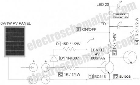
Circuit of the LED solar lantern lights presented here is built around one 6V/1W Solar Panel (PhotoVoltaic Panel) and a 4V/800mAh Lead-Acid Battery. Here, commonly available 5mm White Straw Hat LEDs are used as the light source.
DC 6V supply from the solar panel is fed to the rechargeable battery through diode D1 (1N4007) and resistor R1 (15R). Diode D1 functions as a reverse current protector and resistor R1 limits the battery charging current to a safe value. Transistor T1 (BC548) is here wired as an automatic switch to control the LED driver transistor T2 (SL100). T1 disables T2 when the circuit receives sufficient power output from the solar panel.
Switch S1 is an ordinary power on/off switch. Finally, resistor R4 determines the operating current of the white LED (LED 1 – LED 20) assembly. No-load voltage of the solar panel is near 7.2Volt. When connected with the circuit, the PV panel gives around 170mA of current at 6VDC output in middling sunlight, which is more than enough for this circuit. When fully charged, no-load output voltage of the 4V lead-acid battery is near 4.6Volt. According to datasheet, Forward Voltage of the 5mm (actually 4.8mm) White Straw Hat LED (used here) is 3 to 3.2volt, and maximum Continuous Current is about 20mA (Peak Current 30mA).
(View)
View full Circuit Diagram | Comments | Reading(1808)
RC Servo Tester with 555 IC
Published:2013/9/2 20:53:00 Author:lynne | Keyword: RC Servo Tester with 555 IC

RC Servos basically come in three different sizes (micro, standard, and giant) to accommodate the type of RC models they are being used in. All RC servos have a three wire connector. One wire supplies positive DC voltage (usually 5 V) . The second wire is for voltage ground (0V), and the third wire is the signal (control) wire.
The servo motor can be moved to a desired angular position by sending PWM (pulse width modulated) signals on the signal (control) wire.Usually, a pulse of width varying from 1 millisecond to 2 milliseconds in a repeated time frame is sent to the servo for around 50 times in a second. The width of the pulse determines the angular position.
For example, a pulse of 1 millisecond moves the servo towards 0°, while a 2 milliseconds wide pulse would take it to 180°. The pulse width for in between angular positions can be interpolated accordingly. Thus a pulse of width 1.5 milliseconds will shift the servo to 90°. It must be noted that these values are only the estimations. The practical range of pulse width is 0.2ms to 2.5ms, and frequency is 20Hz to 60Hz.
Notes
Prototype was tested with a “Tower Pro Micro Servo”. Servo test socket “J1” in the circuit is a standard 3-pin male header. In case of any difficulty, you can use 3 flying leads with alligator clips as test probes
S1 is a “Push-To-On” switch works as a “Test Switch”
LED 1 is added to indicate the output status of the tester
Try to use a precision 4K7 trimpot as P1
Note that, here the control pulses have a maximum voltage near-equal to the input voltage (5V) of the tester circuit. This can be a problem if your servo expects a 3V control signal
It is good to add a 100µF/16V capacitor, as a buffer, across the 5V DC supply (VCC & Ground)
Change the values of R1, P1, R3 and C2 if necessary/when demanded by the RC Servo under test. Before testing an RC servo, carefully refer its technical datasheet (View)
View full Circuit Diagram | Comments | Reading(2258)
PCB Drill Speed Controller with 555 Circuit
Published:2013/9/2 20:48:00 Author:lynne | Keyword: PCB Drill Speed Controller with 555 Circuit
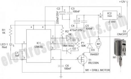
Described here is a simple, inexpensive and useful circuit for electronics hobbyists. The circuit is nothing but a PCB drill speed controller, which can be used to control the speed of any 12VDC small pcb drilling units. Such portable units are now widely available, and even a hobbyist can make it without too much difficulty.
In this circuit, the renowned timer chip LM555 (IC1) is used as a PWM circuit. The whole circuit can be powered from a standard 12VDC supply, capable of sourcing ample current to the PCB drill motor. As you may noted, power supply for the PWM circuit is down-converted and regulated with the help of a 3-pin fixed regulator chip LM7805 (IC2). This will improve the circuit stability. Precision 50K trimpot P1 is the variable drill speed controller. Finally, a logic-level power Mosfet IRL 530N (T1) is used as the output drive element. This IRL530N mosfet (available in TO-220 package) can handle current upto 27A! Fast switching and Low on-resistance – RDS (on) – are other attracting features. IRL 530N is universally preferred for all commercial-industrial applications at power dissipation levels to approximately 50 watts.
Drill Speed Controller Notes
PWM (Pulse Width Modulation) is an efficient way to vary the speed and power of electric DC motors. The described circuit can be used to vary the speed of small electric PCB drill.The circuits can quite easily be built on a standard prototyping board. The power component (IRL510N) must be connected to the power rails and the drill motor with quite thick wires and cables.As used here, a Power MOSFET motor driver is better than the traditional driver because it is working at a higher switch frequency, and this also avoids the unnecessary voltage drop and power loss
Electrically a DC motor can be viewed as a series RL network with a voltage generator. The generator represents the back electromotive force (BEMF) generated by the motor’s rotation and which opposes the electromotive force of the supply. Diode D3 (1N4007) is added to protect the electronics from BEMF. Diode “MBR 1645” is a better alternative
STP22NE10L (100V/<0.085R/22A) can be used in lieu IRL510N (100V/0.10R/17A)
12VDC /2A powered prototype tested with a 12V (1A) Small PCB Drill Press (View)
View full Circuit Diagram | Comments | Reading(1773)
Industrial Battery Charger Project Kit Circuit
Published:2013/9/1 20:49:00 Author:lynne | Keyword: Industrial Battery Charger Project Kit Circuit

The assignment is intended for charging battery(s) by DC from AC supply of power. DC power supplied for a battery’s charger is a derivative from a thyristor controlled rectifier mechanism. AC supply of power is useful to a link rectifier consisting of diodes and a TRIAC achieving preferred power from the micro controller.
This assignment of industrial battery charger brings into use zero crossing point of the waveform which is sensed by a comparator whose productivity is then supplied to the micro controller. The micro controller endow with necessary delay in triggering control to a TRIAC via opto isolator edge. As a final point the power is supplied to the load via triac in succession with the linking rectifier. The DC output which is rectified and controlled is provided to the load i.e., a resistor employed in our project as a substitute of a battery. The DC voltage thus produced is calculated by utilizing a multi-meter. In this industrial battery charger project we have used a microcontroller which is from 8051 family which is edged via push button keys employed for rising or lessening the DC voltage for appropriate charging reasons.
This particular project can be improved further by employing direct 230 volt power supply rather than 12 volt AC to the linked rectifier for obtaining high voltage to control for charging numerous of batteries connected in a sequence. (View)
View full Circuit Diagram | Comments | Reading(1162)
Run/Stop Relay
Published:2013/9/1 20:47:00 Author:lynne | Keyword: Run/Stop Relay

Safety is a major concern in a good many motor-driven applications. This is true in industrial applications where motion starts when power is applied and especially true when power is restored after an outage. In such cases, unwanted or unexpected motion is a risk to life or limb. The most simple solution to this problem is the simple, time-proven Run /Stop Relay Circuit.
With this control circuit, motion cannot commence (or restart) without the operator’s specific pushbutton command. While simple, there are numerous variations and enhancements as you will see, and the benefits are clearly obvious. (View)
View full Circuit Diagram | Comments | Reading(1208)
Momentary Switch with 555 circuit
Published:2013/9/1 20:43:00 Author:lynne | Keyword: Momentary Switch with 555 circuit

Based on NE555 this circuit turns on and off the IC output by a momentary switch. In other words it works as a mechanical latching relay, but the circuit backs to the start condition when you switch off the power supply. This feature is often required in automotive devices. No relay contacts are used, infact I connected the output to a led.
Once the momentary switch circuit is supplied the output (pin 3) keeps off because pin 2 and 6 are at half voltage. When the button is pressed Q1 turns on within a fraction of second because of the capacitor, while Q2 keeps off. By switching on Q1 leads pin 2 and 6 to low voltage, then the output gets high. When the button is pressed again Q2 switches on and leads pin 4 to low voltage (I used a pull up resistor), then the circuit takes the start condition. (View)
View full Circuit Diagram | Comments | Reading(1091)
Arduino Panic Alarm circuit
Published:2013/8/30 2:19:00 Author:lynne | Keyword: Arduino Panic Alarm circuit


Arduino is a family of microcontrollers (tiny computers) and a software creation environment (Arduino IDE) that makes it easy for you to create programs (called sketches) that can interact with the physical world. The Arduino environment has been designed to be easy to use for beginners who have no software or electronics experience. However, try to learn more/refresh your knowledge about arduino platfrom, before constructing this circuit. If you are new to Arduino, this link will help you get started http://arduino.cc. In addition, there is an active and supportive Arduino community that is accessible worldwide through the Arduino forums.The forums offer project development examples and solutions to problems that can provide inspiration and assistance as you pursue your own projects. Here is a simple Arduino guide for beginners www.me.umn.edu/courses/me2011/arduino/arduinoGuide.pdf
Panic Alarm circuit consists of two equally important parts. The first part is the ready-made Arduino Microcontroller board, and the second part is an interface circuit which can be wired on a piece of prototyping board. You can use any standard 9V battery to power the whole circuit, and the Push-ON (push ‘n’ hold) switch (S1) to activate the alarm function. An additional Electro-Magnetic Relay (EMR) is also attached to the interface circuit. With the help of this relay, it is easy to energize other (external) high-power blinkers or beepers, if necessary.
Panic Alarm Lab Notes
Prototype was constructed & tested using “Arduino UNO-R3” board
Sketch created,compiled & uploaded (to Arduino board) using Arduino IDE0022
Piezo-Speaker in the circuit is a “passive piezo-speaker”. Do not use an “active piezo-buzzer”
Use standard flexible wires for interconnection between two boards. Keep the wire length as short as possible
A 9VDC/1A SMPS power supply can be used as an alternative to the 9V battery. Remember to keep an eye on supply polarity
A “9VDC/225 Ohm” Electro-Magnetic Relay was used in the prototype. Contact Capacity of the relay (resistive Load) is 10A 250VAC/10A 30VD
(View)
View full Circuit Diagram | Comments | Reading(1205)
Electronic Key Circuit
Published:2013/8/30 2:15:00 Author:lynne | Keyword: Electronic Key Circuit
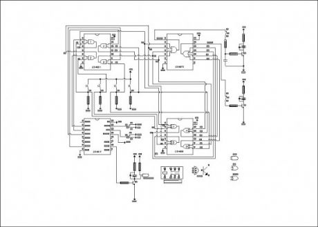
Based on CD4017 and logic gates this electronic circuit switches on a relay if you press four keys in the correct sequence, and backs to the start condition by pressing any key. Once the circuit is supplied the first output of the counter is on and sends the high signal to one input of the CD4081 first gate.By pressing the correct key (P1) the other input of that gate gets on. So pin 3 of the CD4081, then pin 1 of the CD4072 turns on the clock relay K1. The capacitor keeps on the relay for about 0,5 seconds and the key should not be pressed for a longer time.
When all keys are pressed in the correct order the relay K3 turns on. If you press a wrong key the inputs of the related EXOR gate of the CD4030 get a different signal, then the output turns on the reset relay K2 by pin 13 of the CD4072.
(View)
View full Circuit Diagram | Comments | Reading(1179)
RF Based Wireless Remote Control System
Published:2013/8/30 2:13:00 Author:lynne | Keyword: RF Based Wireless Remote Control System

It is often required to switch electrical appliances from a distance without being a direct line of sight between the transmitter and receiver. As you may well know, an RF based wireless remote control system (RF Transmitter & RF Receiver) can be used to control an output load from a remote place. RF transmitter , as the name suggests, uses radio frequency to send the signals at a particular frequency and a baud rate.
The RF receiver can receive these signals only if it is configured for the pre-defined signal/data pattern. An ideal solution for this application is provided by compact transmitter and receiver modules, which operate at a frequency of 434 MHz and are available ready-made. Here, the radio frequency (RF) transmission system employs Amplitude Shift Keying (ASK) with transmitter (and receiver) operating at 434 MHz. The use of the ready-made RF module simplifies the construction of a wireless remote control system and also makes it more reliable.
The current consumption with a supply voltage of near 5.4V is about 10 mA. Since the current consumption is very little,the power can also be provided by standard button cells. Recommended antenna length is 17 cm for 433.92 MHz, and a stiff wire can be used as the antenna. Remember to mount the antenna (aerial) as close as possible to pin 4 (ANT) of the transmitter module.
(View)
View full Circuit Diagram | Comments | Reading(1295)
Trailer Stop & Turn Signal Converter
Published:2013/8/29 1:22:00 Author:lynne | Keyword: Trailer Stop & Turn Signal Converter

If you ever wondered why your trailer Stop/Turn signal lamps are so dim you are not alone. The answer is simply that the typical Stop & Turn Signal Converter/adapter drops a whopping 2.5V! This is VERY significant on a 12V electrical system. This DIY project provides the information you need build a simple, inexpensive converter that reduces this drop to a mere 0.5V @ 2A, and even has sufficient guts to power a 7.5A load. While this documents the most common 4 way (4 wire) system, it may be easily incorporated into more complex systems.
Most automobiles manufactured today have separate Stop and Turn signals — the stop signals are Red, while the Turn signals are Amber. Unfortunately, most trailers do not include the luxury of amber Turn signals, but use the Stop signal also as a Turn signal. The converter takes both input signals and generates one output signal for the trailer. The logic for accomplishing this is simple, but tricky—check out the following truth table. Curiously, when the Stop and Turn signals are simultaneously applied, the trailer Turn signal is “inverted” so that when the vehicle Turn signal is On, the trailer Turn signal is Off, and vise versa.
(View)
View full Circuit Diagram | Comments | Reading(1318)
PIC12F675 Microcontroller Based Security Alarm Circuit
Published:2013/8/29 1:19:00 Author:lynne | Keyword: PIC12F675 Microcontroller Based Security Alarm Circuit
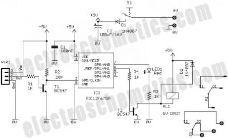
The output of the PIR sensor module (PIR1) is monitored through GP5 (pin 2) of PIC12F675. PIC12F675 is an 8-Pin Flash-Based 8-Bit CMOS Microcontroller. Note that,here the PIC12F675 microcontroller uses the internal clock oscillator at 4.0 MHz. When the motion is sensed, this output is high at about 3.3 V . You could still use this voltage as a valid logic high for IC1 by changing the code , but It is preferred to use this voltage to drive the base of a BC547 transistor (T1) so that at the collector we will have the full swing of the logic voltages.
When power supply is turned on by the on/off switch (S1), IC1 monitors the voltage at the collector of the transistor after a delay of about 60 seconds. This initial delay is introduced deliberately to avoid false triggerings, because the PIR sensor requires an initial stabilization time of about 10 to 60 seconds in order to function properly. A red LED (LED1) is connected to port GP0 of IC1 (pin7) with a current limiting resistor (R3) in series. The LED blinks at a slow rate during this delay time.
After this delay, IC1 starts monitoring the voltage at the collector of T1. The LED blinking pattern is now changed to indicate the “standby” mode. In standby mode, T1 is cut off, and the collector output is at logic high (+5 V). When a “valid” motion is sensed, the high output from the PIR sensor module saturates the transistor and the voltage at the collector drops down to logic low. Consequently, of port GP1 (pin 6) of IC1 goes high to switch on the 5V DPDT relay (RL1) through transistor T2. This output will remain High, as long as the motion exists, and this active condition is indicated by a steady-glow of LED1. DPDT Switching contacts of RL1 can be connected to powerful external lamps and/or alarms.
(View)
View full Circuit Diagram | Comments | Reading(2617)
One-Shot Timer for Energy Saving Lighting
Published:2013/8/29 1:14:00 Author:lynne | Keyword: One-Shot Timer for Energy Saving Lighting
Faced with the situation to control the time that the light is turned on, engineer Radu Preda from Romania has started experimenting with different circuits to save money spent on electricity. He has designed 2 energy saving lighting circuits, the first one uses a relay and the second one uses a optoisolator triac MOC3041 and a normal triac like BTA06-600 and both using the 555 one-shot timer.Note that the circuit is coupled directly to AC mains using the existing system in the building. A switch is used to start the timing and light one or more bulbs. The relay is powered from 12V and its contacts must outstand up to 1kW at 220V.
The LM555 IC is in a monostable configuration. The timing period is set with R4 and C3 and can be calculated with the formula:
T = 1.1 x C3 x R4
With the values from the schematic the working time of the lighting circuit is around 4 minutes. Power is applied through R1, C1, R2 and the voltage is stabilized at a value of 15V with the zener diode PL16Z.
(View)
View full Circuit Diagram | Comments | Reading(1101)
Arduino Based Part Fill Automatic Valve
Published:2013/8/28 1:30:00 Author:lynne | Keyword: Arduino Based Part Fill Automatic Valve
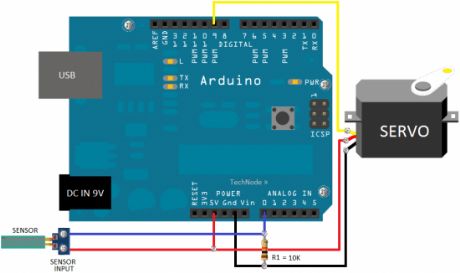
Wanna learn more about the Arduino platform? If you have an irresistible temptation to do some experiments using Arduino microcontroller, just try this simple “electronic” version of a “part fill” valve, wired using an Arduino, a standard hobby servo, and a home-made water sensor. When the Arduino notices the water level inside the rainwater tank is very low , it commands the servo to let the water flow from an alternate source!
Download/copy the simple sketch (Arduino program) included here, verify and upload it to the Arduino board with the help of the Arduino IDE. Here two pieces of stiff wire is used to sense the conductivity in the gap between the water sensor points. When there is more water, there is a higher conductivity. Arduino reads this conductivity, and at the level set by the sketch, turns the servo to release or constrict the flow of water. Needless to say, you should make your own water sensor pad using short-length of closely spaced wires, needles or solder pads. Besides, little skill and patience required to hook up the servo horn with the existing/new valve. The servo horn should crook the town mains water inlet valve open/close to control the flow of water. Zip ties can be used to secure the mechanical connection. Once in situ, try to hot glue the servo. (View)
View full Circuit Diagram | Comments | Reading(1110)
0.3 Second to 10 Hours Timer Relay with 4541 IC
Published:2013/8/28 1:27:00 Author:lynne | Keyword: 0.3 Second to 10 Hours Timer Relay with 4541 IC

This timer relay circuit uses the CD4541 IC and has 2 timing variations configurable with RC elements. The specifications of this timer are:
modes of operation: astable/monostable
the output has a 6A/250V relay with NC/NO contacts
LED signals exiting the timing state
manual programming done with a DIP-switch
12V voltage operation
For the 0.3 second to 10 minutes timer version the potentiometer is 100kΩ, R1 = 9.1kΩ, R2 = 910kΩ, R3 = 220kkΩ and C1 = 100µF.
For the 15 seconds to 10 hours timer version the potentiometer is 1MΩ, R1 = 51kΩ, R2 = 1.2MΩ, R3 = 1.2MΩ and C1 = 1µF.
The operating mode is selected with the third contact of SW1:
ON position = monostable
O position = astable
In order to start the timining you have 2 possibilities: you either connect the START point to ground GND and in this case the timer starts when you connect it to the voltage supply or you can place a switch to start it.
All the resistors are 0.25W and C1 must have a good stability over time.
(View)
View full Circuit Diagram | Comments | Reading(7165)
| Pages:60/2234 At 204142434445464748495051525354555657585960Under 20 |
Circuit Categories
power supply circuit
Amplifier Circuit
Basic Circuit
LED and Light Circuit
Sensor Circuit
Signal Processing
Electrical Equipment Circuit
Control Circuit
Remote Control Circuit
A/D-D/A Converter Circuit
Audio Circuit
Measuring and Test Circuit
Communication Circuit
Computer-Related Circuit
555 Circuit
Automotive Circuit
Repairing Circuit