
Circuit Diagram
Index 58
DIY Water Softener System
Published:2013/9/25 20:03:00 Author:lynne | Keyword: DIY Water Softener System

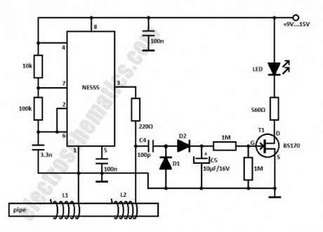
Hard water has a high concentration of minerals, and of these calcium salts are the most troublesome. But there is a solution coming in form of a cheap diy water softener system built with the well-known 555 IC. Actually the price of this diy system is so low that even if this doesn’t work you won’t be upset.
The working principle of the water softener is based on a theory from 1930 which states that an electromagnetic or electric field causes small crystals of calcium carbonate in the water to join together to form larger crystals.
One of the methods to obtain a strong magnetic field is to put a powerful magnet (2.5 gauss) near the water pipe. The second method is the electronic one. Studying a water filter purchased from stores we found that it produces a frequency of about 15 kHz at an amplitude of 15V.
The values of the coils are not known, but my guess is L1 has 9 turns and L2 has 7 turns. Actually you should consider this circuit as a theoretical one.
Therefore this water softener system uses one 555 IC to obtain a rectangular signal that is applied to the water pipe by wrapping two coils with one open ending around it. The coils must have good isolation. Make sure to power the water softener from a isolated power supply because in some areas the water pipes are connected to ground. (View)
View full Circuit Diagram | Comments | Reading(1542)
1.5 Million x High Gain “Transistor”
Published:2013/9/24 20:36:00 Author:lynne | Keyword: 1.5 Million x High Gain “Transistor”


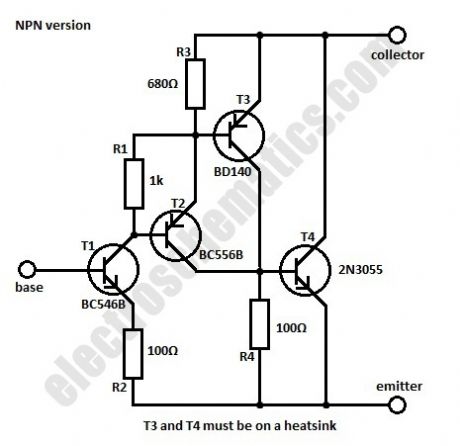
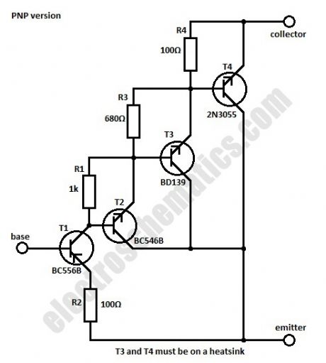
Sometimes we need a transistor with a different characteristic than the normal one for max voltage and current of the collector, maximum power dissipation and amplification. This can be done by using a combination of complementary transistors connected to work as a single NPN or PNP transistor.In the circuits given here we use four transistors for the NPN version of the high gain transistor and four the the PNP one. By choosing the best values for R1, R3 and R4 the total current amplification will be around 1.5 million. The characteristics of the circuit are essentially the same as the 2N3055 transistor.
At 25°C the maximum power dissipation can be up to 115 W while the maximum voltage of the collector is 60 V and max current is 15 A. The saturation voltage is 2 V for the NPN version and 3 V for the PNP one. (View)
View full Circuit Diagram | Comments | Reading(2176)
78XX Voltage Regulator Extension
Published:2013/9/24 20:33:00 Author:lynne | Keyword: 78XX Voltage Regulator Extension

If the 78XX regulator and T1 are mounted on the same heat sink then the transistor is thermally protected. The output voltage is dependent only on the type of the voltage regulator used in the circuit. With the components presented in the schematic the maximum output current is 2 A. T1 is BD242 but for different values of the output current you need to replace some components (download the table at the end).
If higher values are necessary, some components must be changed according to the table presented in the excel file. For currents above 7 A then T1 must be replaced with 2 transistors (T1 and T1*) connected in parallel, each of them having a resistor in emitter, R1 and R1* respectively. Also the bridge rectifier is different. (View)
View full Circuit Diagram | Comments | Reading(1229)
Smoke Alarm Circuit(Photo-interrupter module)
Published:2013/9/24 20:31:00 Author:lynne | Keyword: Smoke Alarm Circuit(Photo-interrupter module)
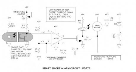
The photo-interrupter is simply an optical coupler with the elements separated with a slot. Anything that enters this slot reduces the current transfer ratio (output current /input current). I used the H21B1 Darlington device since I did not have the H21A1 on hand. I am glad I did, because I learned that it is a better device, requiring far less LED current. Since the H21A1 /H21B1 series is no longer available from DigiKey, I selected a currently available, more inexpensive device—the Sharp GP series—see schematic(s) for details. Sharp appears to be the leader in this product.I did not test the circuit with these devices. (View)
View full Circuit Diagram | Comments | Reading(2566)
Whistle Light Switch
Published:2013/9/23 20:18:00 Author:lynne | Keyword: Whistle Light Switch
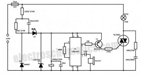
With this whistle light switch you can turn on and off the lighting installation. The main part of this circuit is the UM3763 IC, produced by UMC. The piezo-ceramic buzzer is used here as a microphone and when it receives a tone frequency between 1.2 kHz and 1.8 kHz, the IC’s output will go HIGH. This means that the light will go ON if it was OFF, or go OFF it was ON.
For light control the UM3763 triggers a triac through T1. The supply voltage is taken directly from the main power supply. D1 and D2 diodes are used as rectifiers, and D3 limits the voltage at 3.9 V. D2 LED is used as an indicator of operating or idle state.
Because the whistle light switch circuit is powered from 220V you need to make good isolation and take good precautions. (View)
View full Circuit Diagram | Comments | Reading(1234)
Build Your Own Arduino Board
Published:2013/9/23 20:16:00 Author:lynne | Keyword: Build Your Own Arduino Board
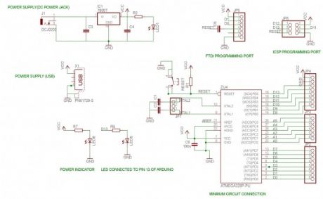
A brief introduction on the Atmega328 chip:
8-bit MCU
32kB Flash Memory
1kB EEPROM
2kB SRAM
23 general purpose IO lines
6-channel 10 bit ADC
SPI and I2C capabilities
(View)
View full Circuit Diagram | Comments | Reading(1224)
Power Indicator for the Water Softener
Published:2013/9/23 20:15:00 Author:lynne | Keyword: Power Indicator for the Water Softener
This power indicator circuit is intended to be used as an extension for the water softener. It might be easier to just place a LED but it is better to make a rectifier that detects the presence of the 15 kHz signal generated by the 555 IC.
The rectifier is connected at the water softener system with C4 capacitor. D1 and D2 diodes are used to obtain a DC voltage that is filtered by C5 capacitor. This voltage turns ON the FET that lights up the LED. When there is no signal from the oscillator the LED will not glow. D1 and D2 = 1N4148. (View)
View full Circuit Diagram | Comments | Reading(1748)
Reed Switch as a Current Monitor
Published:2013/9/22 19:59:00 Author:lynne | Keyword: Reed Switch as a Current Monitor
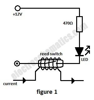

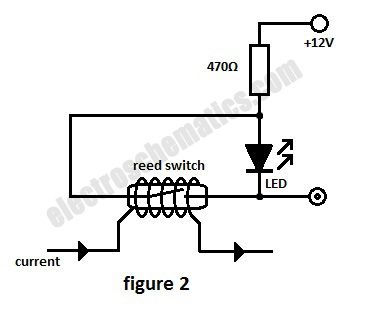
In this current monitoring circuit we use a Reed switch with a LED and a resistor to indicate if is current through a circuit. A Reed switch usually requires between 10 and 100 AT (Ampere-turns = corresponding to the current in a coil multiplied by the number of turns). The lower the AT, the more sensitive the reed switch.
For example a car headlight (both light bulbs) has a current consumption of 7 A or 8 A at 12V so a 50 AT Reed switch requires 7 or 8 turns in order to monitor the current.As soon as one bulb is malfunctioning the current is dropping below half and the switch opens its contact.
(View)
View full Circuit Diagram | Comments | Reading(7743)
Backup Light
Published:2013/9/22 19:55:00 Author:lynne | Keyword: Backup Light
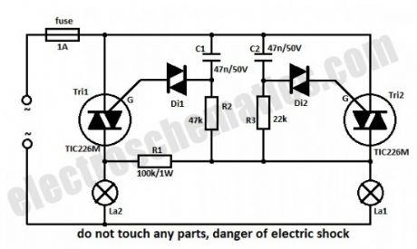
In series with La1 is the Tri2 triac. R3 and C2 form a network delay. As soon as the voltage on C2 is increasing over 30 V, the diac D2 will start to conduct and this will trigger Tri2 resulting in the lighting of La1. The command circuit of La2 is in parallel with the one for La1 but because R2-C1 has a double timing compared to R3-C2 the firing of Tri1 won’t happen when Tri2 conducts.
If La1 is burned out then there is voltage on both RC networks, through La2 and R1 and so the Tri2 will be triggered first but because its current is lower than the holding current it will stop conducting almost immediately. In this situation C1 will continue to charge and shortly Tri1 will trigger.
Because the time constant for La2 is a little higher than the one of La1, then the La2 light intensity will be a little lower. If you want that both light intensity to be the same then choose La1 with a higher nominal power.
Without heatsinks the triacs can outstand powers up to 100 W each, and with heatsinks up to 1000 W. It is not indicated to use light bulbs with power less than 25 W because it might flicker.
(View)
View full Circuit Diagram | Comments | Reading(1447)
Soft Start for 12 Volt Halogen Lamps
Published:2013/9/22 19:52:00 Author:lynne | Keyword: Soft Start for 12 Volt Halogen Lamps

This simple 12 volt halogen lamp soft starter circuit extends the life of the halogen lamps by eliminating the sharp rise in the temperature of the filament; when the filament in cold it has a very low resistance.
How does the halogen soft start circuit works
The C2 capacitor is discharged when the lamp is turned on. As a result, T1 turns on, T2 is blocked and the optocoupler triac is not activated.The initial current for the filament heating is limited at a safe value of 4 A throught the R5 resistor that bypasses the triac.
In this time C2 is charging so that the voltage in the base of T1 begins to decrease. This transistor is blocked now so T1 starts to conduct. The LED inside the optocoupler triggers the triac and so the R5 resistor is practically short-circuited and the halogen lamp lights at maximum intensity.
The S202DS4 optocoupler must be mounted on a relatively big heatsink. The maximum current the the output is about 8 A.
(View)
View full Circuit Diagram | Comments | Reading(2498)
AC Power Monitor IC
Published:2013/9/21 21:11:00 Author:lynne | Keyword: AC Power Monitor IC

This AC Power Monitor continuously watches the AC power line voltage for both under-voltage and missing cycles. When it detects a total of 5 or 6 consecutive missing half-cycles (50mS, 50/60HZ), it drops a relay and starts a timer. A power contactor is slaved to the relay contacts. Its purpose is to protect power-loss sensitive industrial equipment from brief power glitches by preventing immediate restart.
After the specified time delay (2 to 10S), the equipment may automatically restart. Although this may seem like a simple task, note that the condition sensed is the absence of a periodic signal and that the timer may or may not have external power available. electroschematics.com is not really into industrial controls, but this may be the beginning—this is where I spent most of my life.
This function could also be performed by a PLC (programmable logic controller) with a UPS (unterruptable power source), but such would be expensive and consume additional panel space.
Two key components (transformer and relay) are documented on the power monitor schematic — there is no bill of materials.
Power supply
Key to this functioning properly is its power-loss ride-through capability. Note that this circuit continues to time out even after the power is interrupted. To run the circuitry for the entire time period, energy is stored in a large filter capacitor (10,000uf). That way if the power resumes during the timeout period, the timer remains alive and functioning so that the sensitive equipment may not restart.The raw capacitor voltage ranges from about 14 to 24V, and is series regulated to 12V via U2, an LM7812 voltage regulator.
The power transformer (T1) provides low voltage power and power line isolation. Its primary is reconnectable for 115 /230VAC.
Capacitor Bleeder
At the end of the timeout period, the bleeder circuit kicks in to dump the remaining charge. A 4000 series CMOS latch consisting of U3B & U3C is set by the positive transition of U1-3. Should the power resume while the capacitor is bleeding down, the latch is reset via the signal at the collector of Q3 so that the bleeder driver Darlington (Q1 & Q2) turns off. When all of the charge is dissipated by the bleeder resistor (R3), the circuit is free to immediately restart and again monitor voltage glitches.
The MC14093 is a good choice for the power monitor application. It has Schmitt trigger inputs for handling slow input signal transitions, and may be powered by the 12V Vcc. It is identical in pin-out to the more common CD4011. Note that the CD4011 should also function acceptably, but I did not try it in the circuit.
Timer
The timer is the good old 555 (actually, it is the TLC555 due to its low quiescent current). It is configured as a monostable multivibrator that is triggered via a positive voltage at U1-6. To assure that the internal latch of the 555 is set in the proper state during power-up, C7 works against Vcc (rather than common) and U1-2 is held low for 0.5 sec via U3A, C6 and R10.
The timeout period may be increased substantially by increasing the size of the timing capacitor C7. Note that C1 must be adjusted likewise to provide additional ride-through. 60 seconds is not unreasonable.
AC voltage threshold detector
Note that the cathodes of D1 & D2 are unfiltered—this is necessary for rapid sensing of power loss—a filter capacitor would tend to hold up the voltage thus interfering with the voltage loss timer. The filter capacitor (C1) is isolated via D3. The Vbe of Q3 (0.65V) is the voltage threshold comparator. This voltage is multiplied by the ratio of (R4, R5 & R6) to R6.
The function of the voltage threshold comparator is to keep C5 discharged. At each line voltage zero-crossing C5 charges slightly, but requires a full 50mS to reach the threshold of U1-6. Should the voltage remain below the threshold of Q3, C5 starts to charge significantly—if 5 or 6 half-cycles are lost in succession, the voltage across C5 charges to the 8V threshold of U1-6 and triggers the timer.
Proper adjustment of R4 is required. To do so, connect a Variac to the power terminals and reduce the voltage to the desired AC threshold voltage (e.g. 170VAC). Then increase the value of R16 until the LEDs change state. (View)
View full Circuit Diagram | Comments | Reading(1421)
UM3763 Datasheet
Published:2013/9/21 21:09:00 Author:lynne | Keyword: UM3763 Datasheet
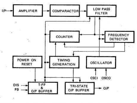
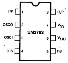
The UM3763 datasheet specifies that this IC is a CMOS LSI circuit which contains analog signal amplifiers and frequency detector for driving motor. It is designed for use in electronic devices and other applications. It is packed with 8 pins DIP.
UM3763 pin configuration
UM3763 features
typical 3V operating voltage
a motor can be driven by connecting a NPN transistor
RC oscillator with one external resistor
on-chip analog signal amplifiers
use of whistle for controlling
the output stage will change when the device senses effective frequency
(View)
View full Circuit Diagram | Comments | Reading(1141)
Appliance Remote Control Arduino Project Circuit
Published:2013/9/21 21:06:00 Author:lynne | Keyword: Appliance Remote Control Arduino Project Circuit
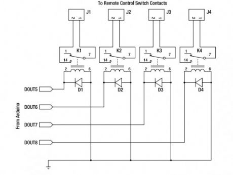
Starting from today I will try to post interesting Arduino projects from around the web. I am novice in this domain but I am giving my best to fully understant it.I must say from the begining that the projects are not developed by me and I will link the original source.This Arduino project uses a general-purpose appliance remote control that you can buy from a hardware store. It can be modified to link it to an Arduino for software control of devices around your house, without having to touch any mains-level wiring.
Parts required:
1 Arduino Duemilanove, Arduino Pro, Seeeduino, or equivalent
1 RF appliance remote control
1 Prototyping shield
4 5V reed relays
4 1N4001 power diodes or similar
4 PCB-mount male connectors
4 line-mount female connectors
10 cm ribbon cable
(View)
View full Circuit Diagram | Comments | Reading(833)
Auto No Break Power Supply Control
Published:2013/9/17 20:13:00 Author:lynne | Keyword: Auto No Break Power Supply Control
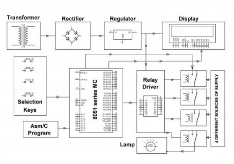
The major aim of this no break power supply project is to supply continuous energy supply to a load, by picking the supply from any spring out of the four like – generator, mains, inverter and solar robotically in the lack of any of the spring. The demand for power is raising day by day and regular electricity cuts are grounds to a lot of troubles in a range of areas such as- houses, hospitals and industries. A substitute arrangement for electricity supply is a must.
In this controller for no break power supply project 4 keys are there to display the particular breakdown of that power source. When out of the four any of the keys is pushed it confirms the lack of that exact spring, keys are linked to micro-controller as incoming signals. 8051 family’s micro-controller is brought into use. The productivity of micro-controller is set to the transmit driver IC, which controls suitable transmit to uphold continuous power supply to the load. The output has to be monitored by means of a lamp taking electricity supply from mains originally. On malfunctioning of the mains power supply (which is activated by pushing the suitable button) the load obtains power supply from the subsequent existing source, like an inverter.
If the inverter too stops working it turn over to the subsequent existing power source and so on. The electricity status, as to which power source delivers the load is also exhibited on an LCD. As it’s not possible to give all four different power springs of supply, one spring with swap switches are given to obtain the similar utility.
The no break power supply can in addition be improved by means of other springs such as wind speed power also and then taking into thought for bring into play the best feasible power whose duty maintains low at that point of time.
(View)
View full Circuit Diagram | Comments | Reading(1221)
Automatic Street Lights Intensity Control Project
Published:2013/9/17 20:12:00 Author:lynne | Keyword: Automatic Street Lights Intensity Control Project
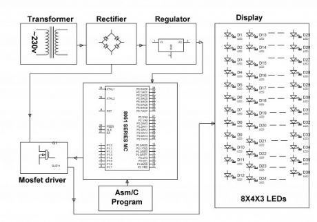
White LED (Light Emitting Diodes) substitutes HID lanterns in road illumination system to add on dim element. 8051 family’s micro-controller is bring into play to control the power by growing pulse width transformed pointers that impels a MOSFET to swap the Light Emitting Diodes accordingly to accomplish most wanted function.
In the current system, maximum lightning over the freeways is completed through HID (High Intensity Discharge lamps), the energy utilization of HID lamps/lanterns are high. The intensity of HID lamps cannot be controlled, in harmony to the necessity, therefore there is a requirement to swap to a substitute way of illumination system i.e., by making use of LEDs. This lighting system is constructed to conquer the disadvantages of High Intensity Discharge lamps.
This lightning system exhibits the utilization of the Light emitting diodes or LED’s as the source of light and its intensity control is variable which can be altered as per the requirement. LED’s use a lesser amount of power and its life span is good, in comparison to the old HID lanterns/lamps. The more vital and motivating characteristic is that the intensity of LED’s can be controlled as per the requirement throughout non-peak hours which is not possible with HID lanterns/lamps.
A bunch of LEDs are brought into play to structure a street light. The micro-controller includes planned instructions which are used for controlling the intensity of lanterns based on Pulse width modulation (PWM) produced indicators. The lights intensity are kept soaring all through the peak hours, because the street traffic have a propensity to reduce slowly during late night hours, the intensity of the traffic also declines gradually till sunrise. Finally it’s totally shuts down at dawn, and it’s all over again restarts at 6pm during the dusk. The course of action is repeated.
(View)
View full Circuit Diagram | Comments | Reading(1637)
Simple LED Tester
Published:2013/9/17 20:10:00 Author:lynne | Keyword: Simple LED Tester

Do not let its extreme simplicity deceive you — this thing is useful! I have made many over the years and have even given some away as gifts. Yes multimeters have a Vf function, but mine barely lights a green, blue or white LED. This is especially useful in checking SMD LEDs that are very easy to otherwise get reverse. It may also be used to check a string of LEDs (one at a time) to make sure that all are installed correctly.
Why 3V?
3V is sufficient to turn on any LED, but is within its reverse break down voltage rating (that is why I did not use the common 9V battery). Short circuit current is approx. 30mA.
LED Tester Construction
I simply soldered (2) 47Ω, ¼W resistors to the two battery terminals and insulated the leads with Teflon tubing — PVC insulation stripped off wires will also work fine. I put a kink toward the end of the lead to keep the tubing in place. I have not had problems with the leads breaking — of course they will eventually fatigue and break, but it is a very simple repair — just avoid bending them sharply.
The battery
I used a 3V lithium battery that I salvaged from a circuit board. Good ones have a voltage that exceeds about 3V. Alternatives are the CR123 or DL123 photoflash battery—or you may simply tape two 1.5V AA or AAA batteries together and connect in series.
Soldering to battery terminals
Soldering directly to battery terminals can be risky. Sometimes it can damage the internal battery connection, so keep this in mind and be willing to sacrifice one in the process. My recommendation is to use a hot soldering iron to get it done quickly. Sometimes solder does not stick—in this case, carefully scrape the terminals with a knife to remove oxide and/or unfriendly plating.
Possible enhancements
How about making a single probe with stranded wires and a pair of spring-loaded test pins?
Storage
I keep mine in a small plastic “jewel case” to prevent accidental discharge.
(View)
View full Circuit Diagram | Comments | Reading(905)
DC Motor Speed Controller Project
Published:2013/9/16 22:18:00 Author:lynne | Keyword: DC Motor Speed Controller Project

The DC motor speed control project is intended to manage the pace of a DC motor by means of an 8051 sequence micro-controller. The pace of DC motor is straightforwardly relative to the voltage functional across its terminals. Therefore, if voltage through motor terminal is different, then pace can too be different.
This assignment makes use of the above theory to manage the pace of the motor by changing the function series of the throb functional to it (commonly acknowledged as PWM control). The assignment bring into play two input keys interfaced to the micro-controller, which are brought into play to manage the pace of motor. Pulse Width Modulation (PWM) is produced at the yield by the micro-controller as per the series.
The schedule can be printed in Embedded C or Assembly language. The standard voltage supplied or the standard current passing all the way through the motor will alter depending on the function series (ON & OFF moment of the pulse), so the pace of the motor will vary. For receiving PWM indications, motor driver’s IC is connected to the micro-controller for distributing much wanted output for pace control of a small DC machine. In addition the DC motor speed control project can be improved by bringing into play power electrical gadgets like IGBTs to get speed control top capacity industrialized motors.
(View)
View full Circuit Diagram | Comments | Reading(1311)
Resistors in Series
Published:2013/9/16 22:14:00 Author:lynne | Keyword: Resistors in Series


In this article we are talking about the resistors in series, how to calculate the equivalent resistance and about the voltage divider. Consider the following picture:
In circuit 1 we have 2 resistors R1 and R2 connected in series and in circuit 2 is shown the equivalent resistor Rs. I is the current that flows through the resistors and VB is the voltage of the battery or power supply. (View)
View full Circuit Diagram | Comments | Reading(778)
Resistors in Parallel
Published:2013/9/16 22:12:00 Author:lynne | Keyword: Resistors in Parallel

In this article we talk about resistors in parallel, the equivalent resistance and the current divider rule for parallel connection of resistors. Let’s consider this circuit:
In circuit 1 we have two resistors R1 and R2 connected in parallel and in circuit 2 the equivalent resistance Rp. I is the total current, I1 is the current that flows through R1 and I2 is the current that flows through R2. (View)
View full Circuit Diagram | Comments | Reading(905)
Flashing Lamp like a Beacon Project Kit
Published:2013/9/15 21:43:00 Author:lynne | Keyword: Flashing Lamp like a Beacon Project Kit
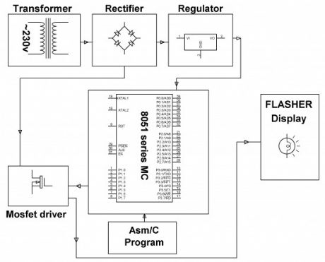
This flashing lamp project is intended to present flash lanterns/lamp creating a flare light by and large brings into play in ship yards, sea beaches etc. It’s also brought into play in center of the deep ocean to caution ships regarding the unseen rocks.
From 8051 family a programmable micro-controller is fit into place to supply the flash light at regular gaps according to the practice pursued at sea coast, ship yards etc. A small electrical energy lantern/lamp of 12Volts is fitted by a power MOSFET in Pulse width modulation (PWM) mode which itself is obtained from a micro-controller.
The task rotation of the Pulse width module has to be altered depending on the kind of purpose. Since the micro controller provides only 5volts drive, it’s not achievable for the MOSFET to be unfailingly change ON at that volt. A crossing point transistor is made use of amid the controller production and the MOSFET for forcing the same. (View)
View full Circuit Diagram | Comments | Reading(910)
| Pages:58/2234 At 204142434445464748495051525354555657585960Under 20 |
Circuit Categories
power supply circuit
Amplifier Circuit
Basic Circuit
LED and Light Circuit
Sensor Circuit
Signal Processing
Electrical Equipment Circuit
Control Circuit
Remote Control Circuit
A/D-D/A Converter Circuit
Audio Circuit
Measuring and Test Circuit
Communication Circuit
Computer-Related Circuit
555 Circuit
Automotive Circuit
Repairing Circuit