
Circuit Diagram
Index 45
Electric windows circuit diagram 2
Published:2013/12/17 20:56:00 Author:lynne | Keyword: Electric windows circuit diagram 2

Electric windows circuit diagram 2 shown in Figure:
(View)
View full Circuit Diagram | Comments | Reading(635)
Electric windows circuit diagram 1
Published:2013/12/17 20:57:00 Author:lynne | Keyword: Electric windows circuit diagram 1
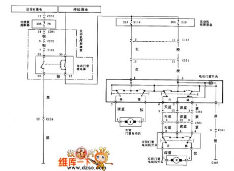
Electric windows circuit diagram 1 shown in Figure:
(View)
View full Circuit Diagram | Comments | Reading(713)
Airbag system circuit
Published:2013/12/17 21:00:00 Author:lynne | Keyword: Airbag system circuit
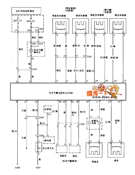
Airbag system circuit shown in Figure:
(View)
View full Circuit Diagram | Comments | Reading(769)
Keyless entry and anti-theft system circuit diagram
Published:2013/12/17 20:59:00 Author:lynne | Keyword: Keyless entry and anti-theft system circuit diagram
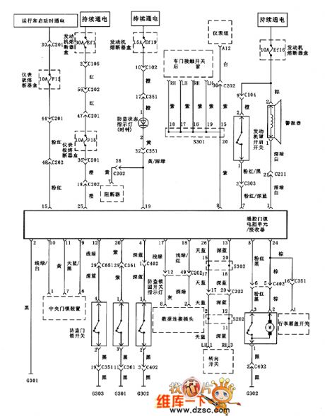
Keyless entry and anti-theft system circuit diagram shown in Fig.:
(View)
View full Circuit Diagram | Comments | Reading(793)
Regal ABS serial data circuit diagram and table
Published:2013/12/17 3:56:00 Author: | Keyword: Regal ABS serial data circuit diagram and table,

Figure regal ABS serial data circuit diagram and table (View)
View full Circuit Diagram | Comments | Reading(738)
Regal automatic transmission with PCM control circuit diagram
Published:2013/12/17 2:37:00 Author: | Keyword: Regal automatic transmission with PCM control circuit diagram,
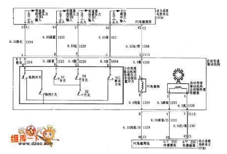
Figure regal automatic transmission with PCM control circuit diagram (View)
View full Circuit Diagram | Comments | Reading(782)
The speed sensor and PNP switch circuit diagram
Published:2013/12/17 2:36:00 Author: | Keyword: The speed sensor and PNP switch circuit diagram,
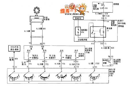
Figure speed sensor and regal PNP switch circuit diagram (View)
View full Circuit Diagram | Comments | Reading(815)
Regal automatic transmission power and light circuit diagram
Published:2013/12/17 2:35:00 Author: | Keyword: Regal automatic transmission power and light circuit diagram,

Figure regal automatic transmission power and light circuit diagram (View)
View full Circuit Diagram | Comments | Reading(711)
Regal power system circuit diagram
Published:2013/12/17 2:35:00 Author: | Keyword: Regal power system circuit diagram,

Figure regal power system circuit diagram (View)
View full Circuit Diagram | Comments | Reading(704)
Regal fuel sensor circuit diagram
Published:2013/12/17 2:34:00 Author: | Keyword: Regal fuel sensor circuit diagram,
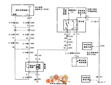
Figure regal fuel sensor circuit diagram (View)
View full Circuit Diagram | Comments | Reading(752)
Regal injector circuit diagram
Published:2013/12/17 2:33:00 Author: | Keyword: Regal injector circuit diagram,
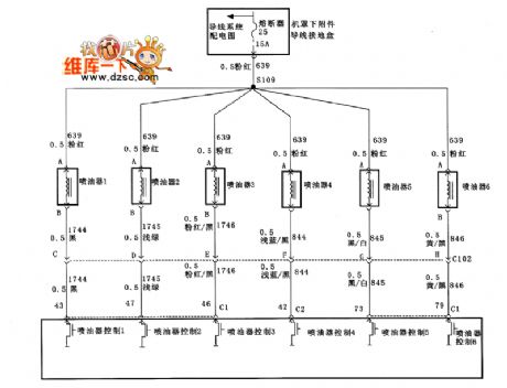
Figure regal injector circuit diagram
(View)
View full Circuit Diagram | Comments | Reading(723)
Regal automatic transmission control circuit diagram
Published:2013/12/17 2:32:00 Author: | Keyword: Regal automatic transmission control circuit diagram,
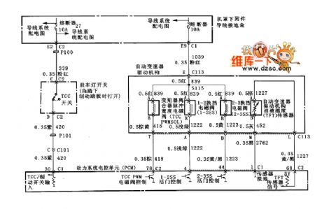
Figure regal automatic transmission control circuit diagram (View)
View full Circuit Diagram | Comments | Reading(863)
Lighting LED constant current source driver circuit diagram
Published:2013/12/17 2:26:00 Author: | Keyword: Lighting LED constant current source driver circuit diagram,


Using this kind of drive circuit, LED directly by the constant current source supply, no feedback, also do not need to compensate, principle as shown in figure 1
Figure 1 LED constant current source driver design
In this circuit, the bias voltage source will be poor stability, large ripple coefficient of external power input into stable constant voltage output, a constant voltage will serve as the input of voltage controlled current source, resulting in a stable and constant current output.
Constant current source driving scheme is often used in simple structure, no high requirements of LED lighting circuit or implement feedback difficult of the combined model of LED lighting circuit. For example, a red (R), green (G), blue (B) 3 kinds of color chip packaging in a pipe inside of three color leds. The RGB - LED according to the additive principle of light, when each color according to the variety of different numerical combination can realize the true color. Through which according to the LED luminous intensity is proportional to the size of the power flow of this feature, RGB three colors of the change of light intensity, set each color has a Nbit brightness, combine 3 Nbit color, can send out to suit the requirements of true color. As shown in figure 2.
Figure 2 tricolor LED driver design (View)
View full Circuit Diagram | Comments | Reading(955)
LED lighting switch power drive circuit
Published:2013/12/17 2:19:00 Author: | Keyword: LED lighting switch power drive circuit,
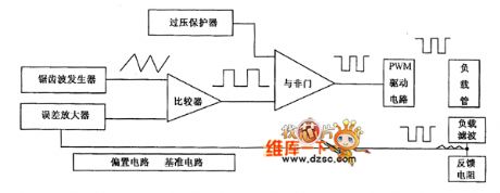
Lighting of high power white LED is a new type of lighting energy saving as a major breakthrough for each, because the technology is not mature at present stage, its not ten points of energy saving effect is obvious. In this case, the LED drive circuit of the power conversion efficiency is a priority problem, for this choice as driving circuit switch power supply scheme.
Practical people designed a dedicated to drive in high power LED switching power supply, its principle as shown. It chooses to switch tube in series with load and the perceptual component, with the capacitive element in parallel type Buck switching converter as the main circuit configuration, the current feedback at the same time, realize the decompression, filtering, steady flow.
The electricity output of the circuit flows through the feedback resistance detection, sampling, and form the feedback signal, feedback signal input to produce a reference voltage of the error amplifier, a reference voltage to cut fixed cycle amplitude of sawtooth wave modulation, formed by the comparator PWM (pulse width modulation) signal. PWM signal amplifying, drive pipe load switch, pulse drive current is produced. Because the output is dc, so add the appropriate external components for filter rectifier load. Load current changes, negative feedback effect of the circuit will change the size of the output duty cycle to achieve the pulse width modulation. Power supply voltage to prevent accidental, fire load tube, also designed the over-voltage protection circuit in the circuit, the circuit when abnormal tube shut off the output load.
Figure principle block diagramThis kind of high power white LED for driving integrated circuit, with a few simple external components that can form a complete pulse modulation type switching power supply, dc constant current output. Integrated circuit can realize frequency is 83 kHz, range of 110 ~ 2720 mA (adjustable) constant current output, voltage ripple and temperature change effect is good.
(View)
View full Circuit Diagram | Comments | Reading(984)
The bus non-contact IC card read and write, circuit diagram
Published:2013/12/17 2:11:00 Author: | Keyword: The bus non-contact IC card read and write, circuit diagram,

Bus non-contact IC card read and write device circuit diagram as shown below:
(View)
View full Circuit Diagram | Comments | Reading(860)
Volvo and walter alarm system circuit diagram
Published:2013/12/17 2:10:00 Author: | Keyword: Volvo and walter alarm system circuit diagram,

Volvo walter, walter alarm system circuit diagram as shown below:
(View)
View full Circuit Diagram | Comments | Reading(711)
Volvo and walter compartment closed circuit diagram
Published:2013/12/17 2:09:00 Author: | Keyword: Volvo and walter compartment closed circuit diagram,
Volvo walter walter assisted the closure of the circuit diagram is shown below:
(View)
View full Circuit Diagram | Comments | Reading(792)
Volvo and walter electric rearview mirror circuit diagram
Published:2013/12/17 2:09:00 Author: | Keyword: Volvo and walter electric rearview mirror circuit diagram,

Volvo walter, walter electric rearview mirror circuit diagram as shown below:
(View)
View full Circuit Diagram | Comments | Reading(820)
Volvo, and power supply circuit diagram
Published:2013/12/17 2:08:00 Author: | Keyword: Volvo, and power supply circuit diagram,

Volvo, and walter power supply circuit diagram as shown below:
(View)
View full Circuit Diagram | Comments | Reading(741)
Volvo and walter S40 cruise control circuit diagram
Published:2013/12/17 2:07:00 Author: | Keyword: Volvo and walter S40 cruise control circuit diagram ,

Volvo walter, walter S40 cruise control circuit diagram as shown below:
(View)
View full Circuit Diagram | Comments | Reading(1688)
| Pages:45/2234 At 204142434445464748495051525354555657585960Under 20 |
Circuit Categories
power supply circuit
Amplifier Circuit
Basic Circuit
LED and Light Circuit
Sensor Circuit
Signal Processing
Electrical Equipment Circuit
Control Circuit
Remote Control Circuit
A/D-D/A Converter Circuit
Audio Circuit
Measuring and Test Circuit
Communication Circuit
Computer-Related Circuit
555 Circuit
Automotive Circuit
Repairing Circuit