
Circuit Diagram
Index 52
Temperature Controlled Relay Circuits
Published:2013/11/24 20:56:00 Author:lynne | Keyword: Temperature Controlled Relay Circuits

This temperature controlled relay circuit is a simple yet highly accurate thermal control circuit which can be used in applications where automatic temperature control is needed. The circuit switches a miniature relay ON or OFF according to the temperature detected by the single chip temperature sensor LM35DZ.
When the LM35DZ detects a temperature higher than the preset level (set by VR1), the relay is actuated. When the temperature falls below the preset temperature, relay is de-energized. The circuit can be powered by any DC 12V supply or battery (100mA min.)
Electronic Temperature-Controlled Relay Schematic
How it works?
The heart of the circuit is the LM35DZ temperature sensor which is factory-calibrated in the Celsius (or Centigrade) scale with a linear Degree->Volt conversion function. The output voltage (at pin 2) changes linearly with temperature from 0V (0oC) to 1000mV (100oC).
The preset (VR1) & resistor (R3) from a variable voltage divider which sets a reference voltage (Vref) form 0V ~ 1.62V. The op-amp (A2) buffers the reference voltage so as to avoid loading the divider network (VR1 & R3). The comparator (A1) compares the reference voltage Vref (set by VR1) with the output voltage of LM35DZ and decides whether to energize or de-energize the relay (LED1 ON or OFF respectively).
Components list:
IC1 : LM35DZIC2 : TL431IC3 : LM358
LED1 – 3mm or 5mm LED
Q1 – General purpose PNP transistor ( A1015,…) with E-C-B pin-out)D1, D2 — 1N4148D3, D4 — 1N400x (x=2,,,,.7)
ZD1 — Zener diode, 13V, 400mW
Preset (trim pot) : 2.2K (Temperature set point)R1 – 10KR2 – 4.7MR3 – 1.2KR4 – 1KR5 – 1KR6 – 33Ω
C1 – 0.1 µF ceramic or mylar capC2 – 470 µF or 680 µF electrolytic cap. (16V min)Miniature relay – DC12V DPDT, Coil = 400 Ω or higher (View)
View full Circuit Diagram | Comments | Reading(1508)
LED as Light Detector
Published:2013/11/24 20:54:00 Author:lynne | Keyword: LED as Light Detector
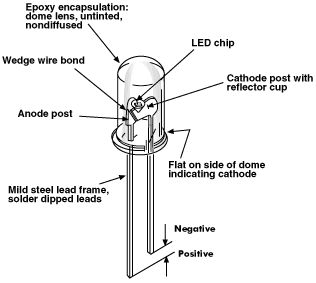
Did you know that the LED can be used as a light detector?In fact green LEDs are the best for this, but all LEDs will detect light and produce a voltage equal to the characteristic voltage-drop. The current they produce is very small, only the super and high bright one can produce a higher output due to the fact that their crystal is more efficient at converting light into electricity.
(View)
View full Circuit Diagram | Comments | Reading(2251)
Homemade Metal Detector Circuit
Published:2013/11/24 20:49:00 Author:lynne | Keyword: Homemade Metal Detector Circuit


This homemade metal detector circuit will help you find objects composed of materials with relatively high magnetic permeability. It is not suitable for buried coins discovery that is not sensitive enough but you can detect pirates treasures!
google_ad_client= ca-pub-9265205501290597 ;google_ad_slot= 6648404198 ;google_ad_width=336;google_ad_height=280;
The metal detector is powered by 2 x 9V batteries, each of it charges with 15 mA. L1 detector coil is part of the sinusoidal oscillator built around transistor T1. Normally, the center frequency of the voltage controlled oscillator (VCO) from the PLL loop that is contained in IC1 is equal to the oscillation frequency of T1. This changes when entering a metallic object (ferrous or nonferrous) in the field induced by L1. S1 is a miniature 2-pole switch.
Meter needle deviation is a measure of frequency change, since the direction of deviation depends on the type of material detected by the coil.The meter tool used for this homemade metal detector is zero as central, +-50µA.
Coil L1 consists of 40 turns of enamelled copper wire, wound on a plastic template with a diameter of about 10 cm. Inductance thus obtained ensure the functioning of the oscillator at a frequency approximately equal to the VCO included in the PLL loop.
Metal detector circuit schematic
Use an oscilloscope to check that pin 2 of IC1 delivers sinusoidal signal with frequency about 75 kHz. Adjust P1 so that fronts rectangular signal from pin 4 to coincide with the peaks of the sinusoidal signal from pin 2. Then, adjust P2 in order to obtain 0 on the meter. Since the neutral zero setting “runs” with the battery’s decreasing voltage it will be necessary to restore it (zero balancing) from time to time during use of the homemade metal detector.
(View)
View full Circuit Diagram | Comments | Reading(1222)
David Moran’s Capacitor Meter Project
Published:2013/11/21 20:49:00 Author:lynne | Keyword: David Moran’s Capacitor Meter Project

Hi guys, I just received an email from David Moran and he sent me his capacitor meter project with pictures and a little presentation. Here are the details and schematic.
Here is the schematic of my capacitor meter I built and have used quite a bit. It will measure from zero to 0.1uf with 300pf at mid range. It is an oscillator that makes noise fed into a bridge circuit that will null out the noise when balanced. Once built, you must clip in known value capacitors and hand calibrate the dial.I built my unit into a cheap push on battery light the output can go to a small audio amp, audio input of a computer, or try a piezo speaker. The noise is rather annoying, so you may want to use a scope to view it if you must test many capacitors.
Capacitor meter schematic
(View)
View full Circuit Diagram | Comments | Reading(963)
Simple Water Detector-Circuit
Published:2013/11/21 20:47:00 Author:lynne | Keyword: Simple Water Detector Circuit
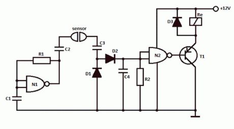
This simple water detector circuit uses alternative voltage in order to prevent the corrosion of the electrodes. It is easy to build and uses N1 as a trigger Schmitt gate which generate the AC. If between the electrodes is a electricity conductor, for example an aqueous solution, then because of the rectification action of D1 and D2, the C4 capacitor is charging.
When the capacitor voltage reaches switching threshold of the N2 trigger Schmitt, the relay will trigger and connect, for example a drain pump. The pump will be disconnected as soon as the electrodes won’t touch the liquid.
Simple water detector circuit schematic
Water detector componentsR1 = 470KR2 = 10M … 22MC1 … C4 = 2.2nFN1, N2 = 1/2 4093D1 … D3 = 1N4148T1 = pnp transistor (BC557) (View)
View full Circuit Diagram | Comments | Reading(1729)
Flashing Lights Circuits
Published:2013/11/21 20:45:00 Author:lynne | Keyword: Flashing Lights Circuits
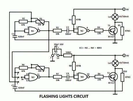
This flashing lights circuit can be used as beacon. The assembly consists basically of two blinking steps that commands two light bulbs. With the help of P1 you can adjust the flashing frequency between some limits.
There are 2 parts for the circuit, the second one works the same way as the other but with the help of a wire bridge or a switch you can choose different operating modes.A bridge between M and 3 means: 2 independent blinks.If there is a bridge between M and 2, then the lamps lights alternatively with a frequency that can be adjusted with P1. And finally there is one more possibility for M and 1, where the lamps blinks at the same time.
The flashing lights circuit works with voltages between 3V and 15V.The lamps voltage must be 2/3 of working voltage. R5 and R10 are chosen so that the lamps are about to light.
Flashing Lamp Lights Circuit Schematic
(View)
View full Circuit Diagram | Comments | Reading(1058)
Telephone Ringtone Generator Circuits
Published:2013/11/21 0:25:00 Author:lynne | Keyword: Telephone Ringtone Generator

This is a simple home telephone ringtone generator circuit which is built with applying only several electronic components / parts. It generates simulated telephone ringtone and requires only DC supply with 4.5V DC to 12V DC voltage.One may possibly use this circuit in ordinary intercom or phone-type intercom. The sound is pretty loud when this circuit is operated on +12V DC power supply. Even so, the volume of ring sound can be adjusted.
Ringtone generator circuit schematic
CD4060B is chosen to produce three kinds of pulses. Preset VR1 is fine-tuned to get 0.3125Hz pulses at pin 3 of IC1. At the same time, pulses obtainable from pin 1 will be of 1.25 Hz and 20 Hz at pin 14. The three output pins of IC1 are connected to base terminals of transistors T1, T2, and T3 through resistors R1, R2, and R3, respectively.
Working with a built-in oscillator-type piezobuzzer generates about 1kHz tone. In this particular circuit, the piezo-buzzer is turned ‘on’ and ‘off’ at 20 Hz for ring tone sound by transistor T3. 20Hz pulses are obtainable at the collector of transistor T3 for 0.4-second duration. Just after a time interval of 0.4 second, 20Hz pulses become again obtainable for another 0.4-second duration. This is followed by two seconds of nosound interval. Thereafter the pulse pattern repeats by itself. (View)
View full Circuit Diagram | Comments | Reading(1447)
Gas Leak Detector Circuit
Published:2013/11/21 0:22:00 Author:lynne | Keyword: Gas Leak Detector
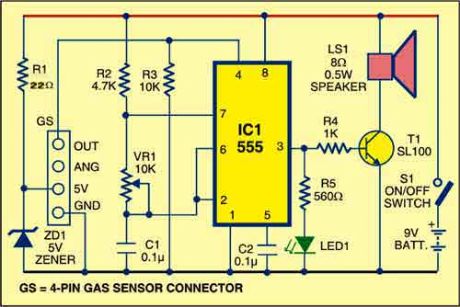
Here is a gas leak detector circuit that detects the leakage of LPG gas and alerts the user through audio-visual indications. The circuit operates off a 9V PP3 battery. Zener diode ZD1 is used to convert 9V into 5V DC to drive the gas sensor module.
The gas leakage circuit uses the SEN-1327 gas sensor module from RhydoLABZ. Its output goes high when the gas level reaches or exceeds certain point. A preset in the module is used to set the threshold. Interfacing with the sensor module is done through a 4-pin SIP header.
Pin details of the gas sensor module are shown in Fig. 2. An MQ-6 gas sensor is used in the gas sensor module. The sensor can also be used to detect combustible gases, especially methane.
Gas leak detector schematic
Whenever there is LPG concentration of 1000 ppm (parts per million) in the area, the OUT pin of the sensor module goes high. This signal drives timer IC 555, which is wired as an astable multivibrator. The multivibrator basically works as a tone generator.
Output pin 3 of IC 555 is connected to LED1 and speaker-driver transistor SL100 through current-limiting resistors R5 and R4, respectively. LED1 glows and the alarm sounds to alert the user of gas leakage. The pitch of the tone can be changed by varying preset VR1. Use a suitable heat-sink for transistor SL100.
google_ad_client= ca-pub-9265205501290597 ;google_ad_slot= 6648404198 ;google_ad_width=336;google_ad_height=280;