
Circuit Diagram
Index 59
Voltage Multiplier LED Driver Circuit
Published:2013/9/15 21:42:00 Author:lynne | Keyword: Voltage Multiplier LED Driver Circuit
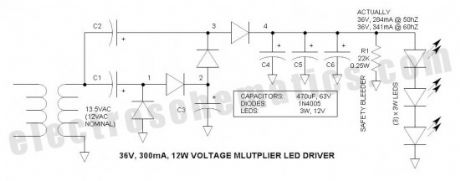
A voltage multiplier is applied as a high source impedance, 36V, 300mA, 12W LED driver. The high source impedance is ideal for driving power LEDs because it accommodates variations in LED junction voltage so that there is minimal change in LED current and brightness. The cascade multiplier is essentially a charge pump that is similar to the popular off-line capacitor limited LED drivers, but offers a substantially higher load current capacity as well as transformer isolation. Note that this circuit topology and application is new to the world.
LEDs are essentially constant voltage devices. Unfortunately, LEDs vary in voltage due to manufacturing variations and temperature. Thus the “constant voltage” is not constant at all—this leads to variations in current when devices are paralleled and also presents a problem when operated from constant voltage power sources—and a serious problem when powered via automotive systems that range from 11 to 14.5V. (View)
View full Circuit Diagram | Comments | Reading(1397)
Battery Level Indicator for 24 Volts Batteries
Published:2013/9/15 21:41:00 Author:lynne | Keyword: Battery Level Indicator for 24 Volts Batteries
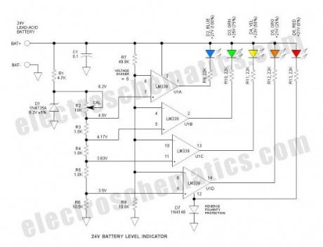
D1 is the voltage reference zener. Tied to this is a string of divider resistors (R2-6) that set the various fixed voltage levels. R7 & 8 form a voltage divider to that divides the battery voltage by a factor of 6. U1 is an LM339 quad comparator that compares the various voltages from the two dividers. The comparator sections have open collector outputs that simply function as switches to operate the LEDs. D7 protects against reverse battery connection.
The LM324 op amp should work OK, but the pin-out is different—and (4) LM741 op amps should also work OK.
It worked as expected and when R2 is calibrated properly, the voltage thresholds are within about 0.1V of stated values. There is no hysteresis so the LEDs tend to flicker slightly at the threshold voltages—this is not a problem.
The LEDs are biased to operate at about 1mA which is reasonably bright if high efficiency LEDs are used—mine were not of the high efficiency type. This current can be adjusted simply by varying the series resistors (R9 through R13). The overall current drain as shown is about 12mA with all the LEDs illuminated. To reduce power, a push-to-test pushbutton is recommended. (View)
View full Circuit Diagram | Comments | Reading(1593)
IR Remote Thyristor Power Controller
Published:2013/9/12 20:28:00 Author:lynne | Keyword: IR Remote Thyristor Power Controller
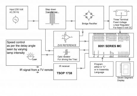
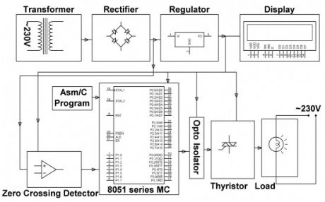
This thyristor power control project is intended to manage the pace of an induction machine for example- fans, by bringing into play a ordinary Television remote. In domestic automatic appliances, ease of using the gadget remotely & controlling the pace of the fan is attained.
An ordinary television remote launches coded infrared statistics to the control panel, which is then acknowledged by an IR antenna or sensor (at the recipient end) interfaced to a micro-controller which is of 8051 family. Each time the button of the TV remote is pressed it launches a particular coded statistics in infrared range. This coded statistics launched by the remote is carried out by the micro-controller to deliver postponed sacking pulses to the thyristor via optical separation. (View)
View full Circuit Diagram | Comments | Reading(1220)
Shadow Sensor Alarm
Published:2013/9/12 20:27:00 Author:lynne | Keyword: Shadow Sensor Alarm
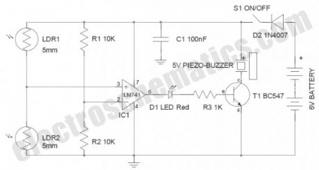
Shadow sensors are widely used to detect the movement of a person in a confined area. Many circuits published earlier have a serious drawback that only one light dependent resistor (LDR) is used for shadow detection.Needless to say, this is not a perfect solution!
Described here is a simple but improved circuit of a smart shadow sensor alarm, which can register a shadow when there is a light difference. Here two 5mm LDRs are used with the popular Op-amp LM741CN to drive an active piezo-sounder when a “valid” shadow is detected. The whole shadow sensor circuit can be powered from four 1.5V AA cells (6VDC), or similar dc supply sources. (View)
View full Circuit Diagram | Comments | Reading(1409)
Non-Contact Human Interface Capacitive Switch
Published:2013/9/12 20:25:00 Author:lynne | Keyword: Non-Contact Human Interface Capacitive Switch

Simple, highly sensitive capacitive ON/OFF switch pads change the state of a latch and turn on an LED without requiring actual physical human contact. The pad may be insulated. A range of 12mm is easily obtained and sensitivity is adjustable.Power is supplied via a common 9V battery.
Central is the 74HC02 CMOS NOR Gate IC. The gate input capacitance is typically only 3pF. To enable a sufficient voltage to change states reliably a 100M bias resistor is recommended. I had to check to see if such a resistor is easily available — yes, it is available from DigiKey at a cost is only $0.52. Or you can fabricate a resistor via series 10 or 22M resistors — that is what I did to obtain 50M. The ‘low sides’ of these resistors are tied to a bias potentiometer so that the static gate input voltage may be set very close to the threshold. Sensitivity is also increased by reducing Vcc to 2.7V (minimum specified operating voltage is 2.0V). I was able to obtain a range of about 16mm using a 50M resistor and paperclip ‘non-contact pad.’
I also experimented with the CD4011 NOR gate—it worked reasonably well, but it has higher gate input capacitance (5pF) and minimum operating voltage is also higher at 3.0V.
A 2N7000 N-Channel MOSFET (Q1) drives a 20mA ultrabright white LED. Note that the gate output voltage may be insufficient to fully turn on the transistor because the maximum Vgs threshold voltage is 3V. Fortunately, most run close to the typical 2.1V. In case one does not work, try another device.
Quiescent battery drain is only 56uA.
The 1M input resistors protect the IC against static discharge and actually allow touching of the pad without danger.
(View)
View full Circuit Diagram | Comments | Reading(1337)
Three Phase Solid State Relay
Published:2013/9/11 20:46:00 Author:lynne | Keyword: Three Phase Solid State Relay

This three phase solid state relay project kit is intended for a system of three phase solid state relay. It integrates three solo phase units where each & every phase is managed independently with the help of a power triac with RC snubber set-up for zero voltage controlling. Opto-isolators are brought into play for each & every phase to obtain controlling signals from a micro-controller which is of 8051 family.
Loads are coupled in sequence with a cluster of triacs being impelled by the opto-isolator. The micro-controller which is from 8051 family is intended to produce output pulses following zero voltage pulse to make sure that the load is getting turned ON at zero cross of the delivered waveform. The zero crossing characteristic of the TRIAC impeller, (an opto-isolator) make certain low sound production, as a result evading unexpected in-rush of current on defying and inductive loads. (View)
View full Circuit Diagram | Comments | Reading(1096)
Industrial Power Controller without Harmonics
Published:2013/9/11 20:45:00 Author:lynne | Keyword: Industrial Power Controller without Harmonics
The industrial power controller project is intended to attain vital cycle switching; a technique to get rid of complete cycle, cycles or fractions of cycles of an AC sign. It is a renowned and aged technique of managing AC power, principally across linear loads for instance heaters brought into play in electric oven.
On the other hand, the idea of attaining the cycle lifting of voltage waveform by bringing into use microcontroller which is of 8051 family can be extremely exact as per the plan engraved in assembly or C language so that the real time average voltage or electric current practiced at the load is fairly lesser than the entire signal if functional to the load. In position of a linear load to be employed in the output, a succession motor or lamp can be applied to make sure the output. One sided outcome of making use of this proposal is an unevenness in the input of the electric current or voltage waveform as the cycles are turned ON or OFF as per the load. (View)
View full Circuit Diagram | Comments | Reading(983)
Power Control for Induction Motor
Published:2013/9/11 20:28:00 Author:lynne | Keyword: Power Control for Induction Motor
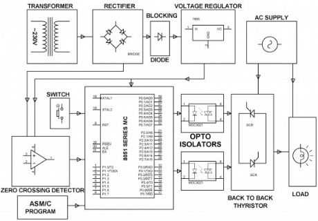
This induction motor power controller project is intended to manage AC power to a load by bringing into play sacking angle direct of thyristor. Effectiveness of such power control is extremely soaring in comparison to any other technique.
This AC power control project brings into play zero crossing end of the waveform which is discovered by a comparator whose productivity is then supplied to the micro-controller from 8051 family. The micro-controller makes available essential postponed trigger control to a couple of SCRs in the course of opto isolator interface. As a final point the power is applied to the load all the way through the SCRs in sequence.
(View)
View full Circuit Diagram | Comments | Reading(1191)
Strobe Lights Project
Published:2013/9/10 19:52:00 Author:lynne | Keyword: Strobe Lights Project
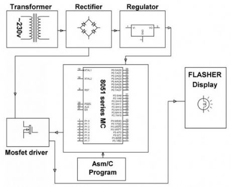
Stroboscopic effects of lights for nightclubs are realized by bringing into play old white Light Emitting Diodes (LEDs) swapping the ejection lanterns/lamps for superior effectiveness at minimal cost. This control is achievable by instantaneously changing the Light Emitting Diodes on & off at elevated volts for small amount of time span. This speedy control of power from complete shine to complete off aids in creating a stroboscopic outcome which is commonly bring into play in discotheque dance floorboards for improved effects.
8051 family’s programmable micro-controller is fit into placed to give such effect being motivated by a MOSFET for group of Light Emitting Diodes. The microcontroller as per schedule produces ON/OFF commands at lofty rate as a result providing the stroboscopic effect of lights. Since the controller provides merely 5volts drive, it’s not achievable for the MOSFET to be constantly be switched ON at that high voltage. A crossing point transistor is made use of amid the controller productivity and the MOSFET for driving the same. (View)
View full Circuit Diagram | Comments | Reading(855)
SCR Phase Control Dimmer Circuit
Published:2013/9/10 19:51:00 Author:lynne | Keyword: SCR Phase Control Dimmer Circuit
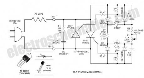
This SCR phase control works much like the common TRIAC dimmer, but has numerous advantages including increased current capability, robustness and absence of minimum voltage “snap-on.” A complementary, symmetrical trigger circuit consisting of two PUTs (programmable unijunction transistors) enables firing of two anti-parallel THYRISTORs (SCRs). The circuit makes up a two terminal power device that is simply inserted between the AC power source and load. Besides controlling the intensity of incandescent lighting, it is useful in controlling the speed of universal (commutator brush type) AC motors.
The DIAC is a 28V bidirectional (bilateral) trigger device that is used on virtually all inexpensive phase controls. The trigger voltage is somewhat high for phase control of 115VAC. Years ago, there was a similar low voltage (6 to 8V) trigger device called a Shockley diode. Unfortunately, these never caught on and today are EXTINCT.
The 2N6027 Programmable Unijunction Transistor (PUT) can perform a similar function, but is polarity sensitive so it does not lend itself to TRIAC control. However, if two such PUT trigger circuits are employed for anti-parallel SCRs, some interesting things are apparent. Most important is the ability to control both trigger circuits with a single potentiometer so that both half-cycles are controlled identically. To obtain best balance, the zeners and capacitors must be matched. Both zeners and capacitors are specified for a tolerance of 5%, but I selected mine for better than 1% with my DMM. Purchase a few additional components so that you may obtain a good match.
PUT operation is simple. Its threshold voltage is programmable so that it can trigger at low voltages. In this circuit it is set via the 12V zeners. When the PUT anode voltage exceeds the gate voltage by one junction drop, the PUT fires and dumps the timing capacitor into the SCR gate circuit. It resets when the AC line voltage reverses. (View)
View full Circuit Diagram | Comments | Reading(2606)
555 Voltage Doubler Relay Driver
Published:2013/9/10 19:49:00 Author:lynne | Keyword: 555 Voltage Doubler Relay Driver

These novel relay driver circuits have the ability to pick up a relay with a coil voltage rating equal to double Vcc. After pickup, the relay armature is held via the application of Vcc. Under this condition, the coil power is reduced by the square of the voltage ratio, or to 25%. This is the ultimate in relay economy—the reduction of wasted coil power. In typical relay economy circuits, the coil power may be reduced to 25%, but the series dropping resistor dissipates an equal amount of power. In the voltage doubler relay driver, THERE IS NO SERIES RESISTOR! I believe that these voltage doubler relay driver circuits are new to the world.
The versatile 555 performs this interface function well. It is configured as a Schmitt trigger inverter /driver with two outputs: Totem pole and open collector. When output (pin 3) goes low, Q1 turns on and sources Vcc to the positive side of the coil. At the same time, the reset line (pin 7) goes low and drives the cathode of C1 to -12V. Thus the difference between the collector of Q1 and the cathode of C1 is 24V momentarily. After C1 is discharged, D2 conducts the coil current to common thus applying 12V minus one diode drop to the relay coil.
When the input to the 555 goes low, pin 3 goes high, pin 7 is turned off and the relay drops. At this time C1 starts to recharge—its charge time constant is 0.47sec so it will be ready to fire again in about 2sec.
The input logic threshold may be adjusted down to TTL levels via connecting the suggested voltage divider (R4 & R5) to pin 5 (see schematic). This is recommended for only the CMOS TLC555 device. Otherwise, the standard bipolar 555 should work fine. (View)
View full Circuit Diagram | Comments | Reading(992)
ON OFF Touch Switch with 555
Published:2013/9/9 20:27:00 Author:lynne | Keyword: ON OFF Touch Switch with 555
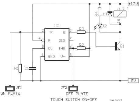
This ON OFF touch switch circuit is based on the well known timer IC 555 (IC1), which drives a relay that acts like a switch. The metal surfaces can have what form we want, but it should be clean and very close to the circuit.Touch plate MP1 in order to close the contact of relay RL1 [ON], or plate MP2 in order to open the contact of RL1 [OFF]. The Led D2 turns on when the contacts of RL1 are closed. Two small pieces of metal can be used as sensor plates.
Components List
R1 = R2 = 3.3MR3 = 10KR4 = 1KC1 = 10nFD1 = 1N4007Q1 = BC547IC = NE55512V relay (View)
View full Circuit Diagram | Comments | Reading(1623)
Zero Voltage Switching (ZVS) for Lamp Life Extender
Published:2013/9/9 20:26:00 Author:lynne | Keyword: Zero Voltage Switching (ZVS) for Lamp Life Extender

This lamp life extender project is intended to create an appliance to enhance the existence of luminescent lanterns or lamps. Luminescent lanterns or lamps show signs of very small resistance in freezing circumstances owing to which it pulls lofty current while turned ON, as a result breakdown is fast.
Frequent switching of lantern or lamps may turn the load at maximum supply voltage. When such random switching takes place while the lantern or lamp is enclosing small resistance (freezing circumstances) then the electric current further go sky-high (at the point of max supply voltage turn ON) resulting in impulsive collapse of the lantern or lamp. The planned project offers an answer by fitting into place a TRIAC in such a manner that the turn ON time is exactly directed by precisely sacking it after noticing the zero cross end of the waveform of delivered voltage. This would outcome in electric current waveform increasing from zero at the moment of switch to peak value, in this manner escalating the lantern or lamp’s life. (View)
View full Circuit Diagram | Comments | Reading(1165)
LED Security Light with PIR Motion Sensor Circuit
Published:2013/9/9 20:24:00 Author:lynne | Keyword: LED Security Light with PIR Motion Sensor Circuit

In this security light circuit, High level (3.3V) output from SB0061 is used to switch on six 5mm white straw hat LEDs through a solid-state switch realized using transistors T1 & T2. PIR sensor modules usually have a 3-pin connection: Vcc (+) , Output, and Ground (-) . The pinout may vary, so it is recommend to check the manufacturer’s datasheet to confirm the pins. Besides PIR sensor module also has a 3-pin jumper selection for single or continuous trigger output mode.
The two positions have labels H and L. When the jumper is at H position, the output remains high when the sensor is re-triggered repeatedly. In position L, the output goes high and low every time the sensor is triggered. So a continuous motion will give repeated high/low pulses in this mode.
The PIR LED light security circuit can be powered from a compact 9V rechargeable battery. Note that the battery charger circuit is not included with the circuit schematic. You can use any suitable external 9V battery charger to re-charge the battery pack.
(View)
View full Circuit Diagram | Comments | Reading(2540)
Touch Sensor Switch Circuit with 555 timer
Published:2013/9/8 20:33:00 Author:lynne | Keyword: Touch Sensor Switch Circuit with 555 timer
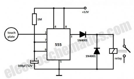
This is a very simple touch sensor switch that is build with the 555 timer IC.You just need to touch the metal plate and the relay gets energised and is kept in this state for about 100 seconds, then is released.
This kind of sensor switch is suitable for making touch operated bells, buzzers of small toys which operate for a small time and then switch off automatically.
The input impedance of the trigger is very high and the touch sensor switch can be triggered by the voltage induced in the human body. The relay is a 12 V DC relay operating at currents less than 200 mA.
(View)
View full Circuit Diagram | Comments | Reading(1732)
Test Human Reaction Time with the 555 IC
Published:2013/9/8 20:32:00 Author:lynne | Keyword: Test Human Reaction Time with the 555 IC
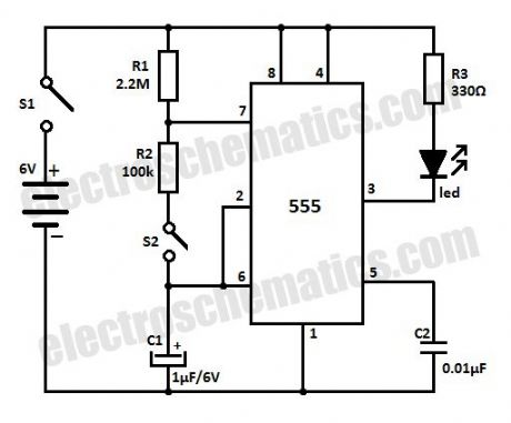
With this simple circuit that is built with the 555 IC you can test human reaction time. You can find out how fast do you react by trying to catch a flashing LED.How does the human reaction tester works?
When S1 is ON the circuit acts as a astable multivibrator and the LED is lit for about 0.1 second and is flashing every 1.5 seconds. Since the human reaction time is more than this (>100 ms) it will be quite difficult to catch the LED when is ON. If you press S2 within that 0.1 second period of time when the LED is ON then the discharging of C1 stops and the LED stays lit.
You can change the ON and OFF alternating periods by changing the values of R1 and R2 or C1 to suit your preferences.
(View)
View full Circuit Diagram | Comments | Reading(1663)
LED Security Light with PIR Motion Sensor
Published:2013/9/8 20:31:00 Author:lynne | Keyword: LED Security Light with PIR Motion Sensor

In this security light circuit, High level (3.3V) output from SB0061 is used to switch on six 5mm white straw hat LEDs through a solid-state switch realized using transistors T1 & T2. PIR sensor modules usually have a 3-pin connection: Vcc (+) , Output, and Ground (-) . The pinout may vary, so it is recommend to check the manufacturer’s datasheet to confirm the pins. Besides PIR sensor module also has a 3-pin jumper selection for single or continuous trigger output mode.
The two positions have labels H and L. When the jumper is at H position, the output remains high when the sensor is re-triggered repeatedly. In position L, the output goes high and low every time the sensor is triggered. So a continuous motion will give repeated high/low pulses in this mode.
The PIR LED light security circuit can be powered from a compact 9V rechargeable battery. Note that the battery charger circuit is not included with the circuit schematic. You can use any suitable external 9V battery charger to re-charge the battery pack.
Notes
The PIR sensor requires an initial stabilization time of about 10 to 60 seconds in order to function properly. During this time, the sensor gets familiar with the surrounding environment, and any motion in its field of view should be avoided.
As stated above, the PIR Module needs a “warmup” period of about 10 to 60 seconds, during which time it’s adapting to ambient conditions and may trigger randomly. So anyone using this simple circuit needs to be prepared to accept random triggering for a while after startup.
Due to the high sensitivity of PIR sensor device, it is not recommended to use the module in the following or similar condition:
in rapid environmental changes
in strong shock or vibration
in a place where there are obstructing material (eg. glass) through which IR cannot pass within detection area.
exposed to direct sun light
exposed to direct wind from a heater or air condition
A 9V /250mAh NI-MH Rechargeable battery is used to test the prototype. If possible, try to use a 9V type with higher current capacity.
Value of R3-R4-R5 is optimised for the white LEDs used in the prototype. This needs a “re-touch”, based on the type of white LEDs used in your circuit. (View)
View full Circuit Diagram | Comments | Reading(1960)
220V Solid State Flashing Lamp with 555
Published:2013/9/5 19:59:00 Author:lynne | Keyword: 220V Solid State Flashing Lamp with 555

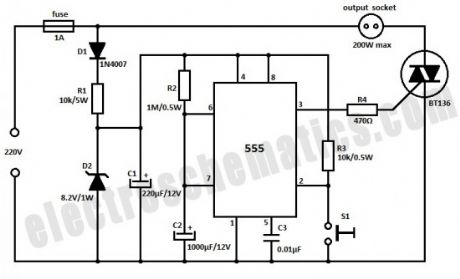
This 220V mains operated solid state flashing lamp circuit uses a 555 timer IC to control the ON and OFF times of a triac which controls power to the load. The power supply for the IC is obtained by half wave rectifier (D1), a stabilizer circuit (D2 and R1) and filter capacitor C1. The lamp stays ON for about 1 second and OFF for about 0.7 seconds. You can change these times by choosing other values for R2 and R3. (View)
View full Circuit Diagram | Comments | Reading(3406)
Delayed Automatic Power OFF
Published:2013/9/5 19:57:00 Author:lynne | Keyword: Delayed Automatic Power OFF
This circuit is build with the 555 IC and will automatically turn off the power after 20 minutes. You can use the circuit to turn off the porch light after you lock the house or similar other uses.The 555 timer is operated as a monostable and a momentary push on S1 switch makes the output go high which triggers the triac and makes power available in the socket.
The IC output goes low again when C2 has charge up to 2/3 of the supply voltage. This process takes about 20 minutes. C2 should have low leakage otherwise it will charge very slowly and in cases of excessive leakages may not charge to full value at all. Power supply for the timer is provided by half wave rectifier D1, voltage dropping resistor R1, zener diode D2 and filter capacitor C1.
(View)
View full Circuit Diagram | Comments | Reading(2088)
LDO 5V Voltage Regulator with MCP1755
Published:2013/9/5 19:57:00 Author:lynne | Keyword: LDO 5V Voltage Regulator with MCP1755

This LDO (low-dropout) voltage regulator is built with MCP1755 and can deliver 5V and currents up to 300 mA with a input voltage range between 5.5V to 16V. The LDO output is stable when using only 1 µF of output capacitance. Ceramic, tantalum or aluminum electrolytic capacitors may all be used for input and output. Overcurrent limit and overtemperature shutdown provide a robust solution for any application. (View)
View full Circuit Diagram | Comments | Reading(1333)
| Pages:59/2234 At 204142434445464748495051525354555657585960Under 20 |
Circuit Categories
power supply circuit
Amplifier Circuit
Basic Circuit
LED and Light Circuit
Sensor Circuit
Signal Processing
Electrical Equipment Circuit
Control Circuit
Remote Control Circuit
A/D-D/A Converter Circuit
Audio Circuit
Measuring and Test Circuit
Communication Circuit
Computer-Related Circuit
555 Circuit
Automotive Circuit
Repairing Circuit