Basic Circuit
Battery Level Indicator for 24 Volts Batteries
Published:2013/9/15 21:41:00 Author:lynne | Keyword: Battery Level Indicator for 24 Volts Batteries | From:SeekIC

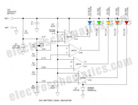
D1 is the voltage reference zener. Tied to this is a string of divider resistors (R2-6) that set the various fixed voltage levels. R7 & 8 form a voltage divider to that divides the battery voltage by a factor of 6. U1 is an LM339 quad comparator that compares the various voltages from the two dividers. The comparator sections have open collector outputs that simply function as switches to operate the LEDs. D7 protects against reverse battery connection.
The LM324 op amp should work OK, but the pin-out is different—and (4) LM741 op amps should also work OK.
It worked as expected and when R2 is calibrated properly, the voltage thresholds are within about 0.1V of stated values. There is no hysteresis so the LEDs tend to flicker slightly at the threshold voltages—this is not a problem.
The LEDs are biased to operate at about 1mA which is reasonably bright if high efficiency LEDs are used—mine were not of the high efficiency type. This current can be adjusted simply by varying the series resistors (R9 through R13). The overall current drain as shown is about 12mA with all the LEDs illuminated. To reduce power, a push-to-test pushbutton is recommended.
Reprinted Url Of This Article:
http://www.seekic.com/circuit_diagram/Basic_Circuit/Battery_Level_Indicator_for_24_Volts_Batteries.html
Print this Page | Comments | Reading(3)

Article Categories
power supply circuit
Amplifier Circuit
Basic Circuit
LED and Light Circuit
Sensor Circuit
Signal Processing
Electrical Equipment Circuit
Control Circuit
Remote Control Circuit
A/D-D/A Converter Circuit
Audio Circuit
Measuring and Test Circuit
Communication Circuit
Computer-Related Circuit
555 Circuit
Automotive Circuit
Repairing Circuit
Code: