
Circuit Diagram
Index 61
Automatic Fan Controller
Published:2013/8/28 1:26:00 Author:lynne | Keyword: Automatic Fan Controller

The automatic fan controller circuit shown in the schematic has 2 comparators with different triggering points that are independently adjustable. LM135 or LM335 in a TO92 package is used as a temperature sensor.
The R5 resistor polarizes the temperature sensor. On the non-inverting input of TL072 is applied a voltage that varies according to the temperature with 10mV/K. R1, R2, P1 and R3, R4, P2 form 2 resistive dividers whose voltage is applied on the inverting inputs of both comparators. Adjustment of the threshold point is done with P1 and P2.
When the non-inverting input voltage exceeds the threshold point (set by P1 and P2) the TL072 goes from Low to High state. The first comparator drives the fan motor with help from 2 transistors (T1 and T2) connected in a Darlington configuration as long as the temperature read by the sensor is higher than the level set with P1.
The threshold level of the automatic fan controller is made with a thermometer. Place the sensor on the surface which temperature you want to monitor. Read the temperature with the thermometer and adjust the threshold level of the fan with P1 at the desired temperature.
The second comparator goes from Low to High state when the threshold level adjusted with P2 is exceeded. You can connect a relay on the OUT output (using the circuit from figure 2) to disconnect or connect a second fan or other type of equipment.
You can connect a red LED in series with one 1kΩ resistor to signals when it reached the desired temperature.
(View)
View full Circuit Diagram | Comments | Reading(1805)
Ultrasonic Dog Repeller Circuit
Published:2013/8/27 2:29:00 Author:lynne | Keyword: Ultrasonic Dog Repeller Circuit

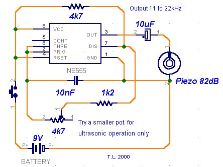

This ultrasonic dog repeller circuit will chase away angry dogs. It is build with the all known 555 circuit, a buzzer and a little ferrite transformator. The ultrasonic frequency must be set with a dog nearby.
Circuit number 1 uses the well known NE555 IC, couple of components and a EE15 ferrite transformer. Adjust R3 at resonance frequency of the piezo transducer for maximum aplitude of the repeller ultrasonic sound. At 30 KHz this can reach a value of 108 Vpp. Without the piezo the output voltage is around 200 Vpp.
(View)
View full Circuit Diagram | Comments | Reading(3821)
70 Watt MOSFET Audio Amplifier
Published:2013/8/27 2:26:00 Author:lynne | Keyword: 70 Watt MOSFET Audio Amplifier
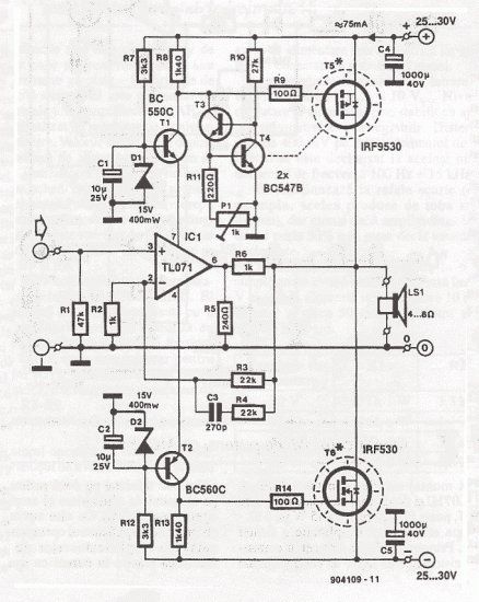
This simple power mosfet audio amplifier circuit, with TL071C and 2 MOSFETs (IRF9530 and IRF530) can deliver up to 45 Watts on 8 Ω speaker. This schematic is based on Siliconix application and on variations of voltage on the 2 resistors that are serial inserted on the voltage supplier of the operational amplifier driver. The MosFet transistor must be mounted on a heatsink with at least 1K/W.
Amplifier’s efficiency is 70%, distortions at cut frequency were at most 0.2% at 20Hz on 8 Ω and 10W. With a power supply of ± 30V the mosfet audio amplifier can deliver 45W on 8 Ω and 70w on 4 Ω. Remember that this audio amplifier is not protected on shortcircuits so everytime you switch on check to see if the speaker is connected.
(View)
View full Circuit Diagram | Comments | Reading(2141)
TDA2030 10W Audio Amplifier Circuit
Published:2013/8/27 2:21:00 Author:lynne | Keyword: TDA2030 10W Audio Amplifier Circuit
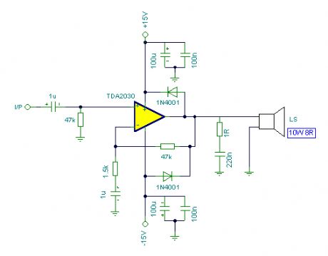
TDA2030 audio amplifier can output 20 W but in this schematic we have reduced the power to 10 Watts and we use 10 W speakers. The input sensivity is around 200 mV and the amplifier is set by the 47 k and 1.5 k resistors.
(View)
View full Circuit Diagram | Comments | Reading(1419)
Dim 12V Light Bulb with 555 IC
Published:2013/8/26 1:23:00 Author:lynne | Keyword: Dim 12V Light Bulb with 555 IC
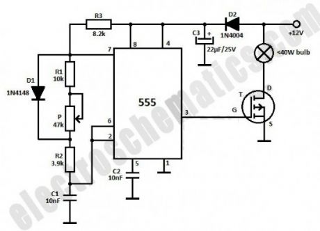
This light dimmer is used to dim the intensity of 12V light bulbs using the well-known 555 timer that is configured as an astable multivibrator. The pulses from pin 3 are used to control the VMOS transistor BUZ20, BUZ72 or 10N10. The maximum dissipated power must not exceed 40 watts. You may use the transistor without a heatsink if the power does not exceed 10 watts.The 555 IC powering is done through D2 diode and is filtered using C3 capacitor. The resistors can be 0.25W or 0.5W with a tolerance of ±5%.
(View)
View full Circuit Diagram | Comments | Reading(2554)
Adaptive Lighting System for Automobiles
Published:2013/8/26 1:15:00 Author:lynne | Keyword: Adaptive Lighting System for Automobiles
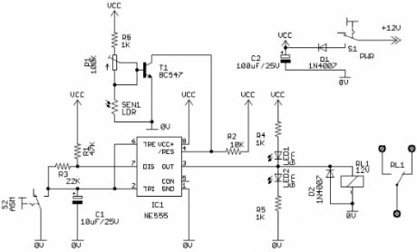
When a vehicle is driven on the highway at night, it is required that light beam should be of high density and should illuminate the road at a distance sufficiently ahead. However, when a vehicle coming in the opposite direction approaches the vehicle with a high-beam headlight, driver of that vehicle will experience a glare, which may blind him. This dazzle effect is one of the major problems faced by a driver in night driving. To avoid this impermanent blindness, a separate filament is usually fitted in the “dual-filament” headlight bulb in a position such that light beam from this second filament is deflected both down and sideways so that the driver of the oncoming car is not blinded. In practice, one mechanical dimmer switch is used by the driver to manually select high (bright) or low (dim) headlight beam. However, this is an awkward task for the driver especially during peak traffics.
Prominent Features:
12V automobile battery powered automatic switching circuit with negligible current consumption in standby mode
Reliable and weatherproof light sensor module (Cds photocell)
Independent variable control to set the “light detection sensitivity to avoid false triggering caused by the influence of other light sources like streetlights
Optional selector switch for “Automatic Signaling Mode” (ASM). In this mode, dim/bright control of headlight is in pulsed, i.e. headlight automatically changes to dim level from bright level and vice versa in a rhythmic style (like a signal to the other motorists) when light from the front coming vehicle is detected by the light sensor module
“Energy Saving Mode” – If the circuit is in active state, by default, headlights automatically goes off when the vehicle enters in a well-lighted area.
(View)
View full Circuit Diagram | Comments | Reading(2084)
Low Voltage Audio Amplifier
Published:2013/8/26 1:12:00 Author:lynne | Keyword: Low Voltage Audio Amplifier

This experimental (3) transistor class A audio power amplifier delivers 25mW into an 8Ω load, or 50mW into a 4Ω load using only a 1.5V power source. At such low voltages, there are many issues to consider and much to learn. To the best of my knowledge the following information is new to the world.
Background
Months ago, I indicated an intention to write a piece on low voltage transistor application for another of my Single Transistor Amplifier Revisited series. Then a few weeks ago, Daniela, who participates in our forum, asked the simple, but profound question: “what is the minimum operating voltage of a transistor?” While, Mr. Marian attempted to narrow the scope of the question, no answers were given. This is on the heels of a similar article concerning Low Voltage Operation of the 555.
Theoretical minimum vs. practical minimum voltage
For a silicon bipolar transistor, the initial voltage requirement is to exceed the Vbe junction voltage of 0.6V. Then, to be able to current regulate this voltage via a series resistor, the source voltage must be about double this or about 1.2V. (The rule of thumb for shunt voltage regulators is that the source voltage is recommended to be double the regulated voltage.) This is perhaps the theoretical minimum Vcc. The practical minimum takes into consideration low voltage power sources – in this case, the ubiquitous 1.5V single cell battery is perhaps the standard low voltage power source – this is the power source for my circuit.
(View)
View full Circuit Diagram | Comments | Reading(1756)
PIC12F635 Based Door Alarm System
Published:2013/8/22 20:15:00 Author:lynne | Keyword: PIC12F635 Based Door Alarm System
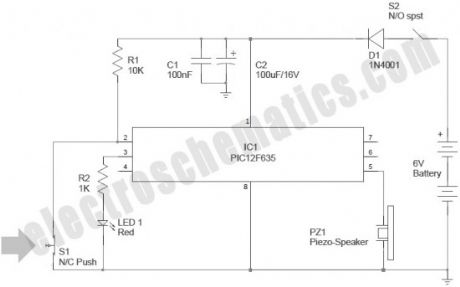
Now you can build your own simple door alarm security system using a tiny microcontroller chip PIC12F635! The circuit is nothing but an aural alert unit, which raises a warning tone when the concerned door is opened by someone. You can install this unit in your front/back door as a security alarm to deter burglars and intruders.The unit can be powered from four 1.5V AA/AAA cells wired in series (6VDC).
After construction and testing, carefully mount switch S1 in the door (or doorcase) so that it is in “open” condition when the door is in closed state. Next, set up the alarm unit at a remote location, and make the interconnection between S1 and the alarm unit using low-voltage cables.
The circuit can be energized by turning the power switch S1 to “On” position. The Red LED (LED1) blinks 3 times when the power is turned on to indicate that the system has been powered up. Then IC1 (PIC12F635) waits for 30 seconds before it starts monitoring the door sensor (S1) status. This delay is introduced deliberately to help the user to “arm” the alarm and move out through the door without triggering the alarm system. After this initial delay, when the IC1 detects S1 is closed (door opened) , it drives the iezo – speaker (PZ1) with a square wave signal, and the piezo – speaker remains on as long as the door is opened. If the door is again closed (and the switch S1 changes to open state) the piezo – speaker will not sleep immediately, but still be on for about 10 more seconds but with a slightly different frequency. (View)
View full Circuit Diagram | Comments | Reading(1169)
Infrared Model Train Detector
Published:2013/8/22 20:13:00 Author:lynne | Keyword: Infrared Model Train Detector
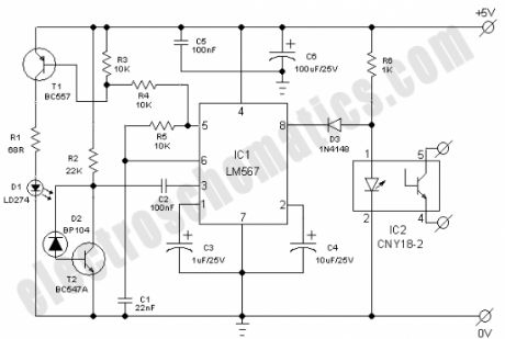
This simple and economical IR model train detector circuit is intended especially for those hobbyists who wish to add a smart sensor to detect trains on their model railway track. As can be seen in the schematic diagram, it comprises of a simple infrared transmitter and receiver wired around the good old PLL Tone Decoder LM567(IC1). It has a working range of around 10 to 50 cm. Output of the detector is galvanically isolated with the help of a standard opto-coupler CNY18-2 (IC2), which can be suitably interfaced to any external circuit for further processing task(s).
Working of the circuit is straight forward. When light from Infrared sender (D1) is relected by the wagon of the model train, IC1 through Infrared photo sensor (D2) receives the recovered signal at its input point (pin3). If PLL (IC1) is locked, its output (at pin8) drops low, thus disabling the optocoupler IC2 for the specific time and this process repeats based on the number of wagons.
Infrared componets D1 and D2 should be mounted such that D2 can only pick up reflected light. When a train passes, the infrared light is reflected at certain intervals, which produces a sort of ‘pulse code’ for the train. Using an external circuit connected through IC2, it is possible to distinguish various model trains from each other using the pulse code! The choice of D1 and D2 is not very critical, but they must be band compatible. Operating point of the detector is dependent on refleted light levels and value of the resistor R2 (here 22K) may need to be ‘tuned’ for optimum performance. (View)
View full Circuit Diagram | Comments | Reading(1874)
555 Fast Reset Timer
Published:2013/8/22 20:05:00 Author:lynne | Keyword: 555 Fast Reset Timer
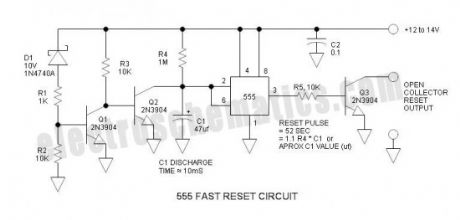

A common problem with on-delay timers is the timing capacitor reset. Typical timers (555 included) rely upon both complete power loss and finite elapsed time to assure that the timing capacitor is fully discharged. If this important detail is ignored, the timeout period is reduced and inconsistent. This 555 timer circuit resets almost instantly when Vcc drops below +10V. This circuit avoids the use of the 555 pin 4 reset feature that often causes more problems than it solves – this anomaly was previously documented in this article: Quirky 555 Timer Reset Function.
The initial application for this circuit was a reset timer in which the output was hard-wired across a reset pushbutton. The terminology is a little confusing because this is a reset timer that resets digital electronics, and the timer itself must reset instantly upon power loss by dumping the charge in the timing capacitor.
When digital components (including some Bluetooth stuff) are interconnected in automotive applications, initialization is sometimes an annoying problem that is complicated if both pieces of equipment do not have the same reset criteria (e.g. one component resets upon complete power loss, while another component resets when Vcc drops only briefly or slightly). In this application, a 50sec reset duration was found to be effective (I cannot provide more information because I was helping someone of a different language in a distant country).
More advanced software features provide a “warm” reset feature that automatically restores lost communications – in such a case, a reset timer is not required.
(View)
View full Circuit Diagram | Comments | Reading(1295)
Electrical Live Wire Detector
Published:2013/8/21 21:46:00 Author:lynne | Keyword: Electrical Live Wire Detector

This circuit can detect only electrical wires connected to the mains (live wire). It has an LED for visual signalization and a buzzer for audio. As the electrician places the detector closer to the electrical wire the LED will flash at a higher frequency.
As you can see the schematic of the wire detector circuit is quite simple. The first stage has the antenna in base of T1; capacitor C1 is used for filtering parasite high frequency signals which are captured by the antenna.
The low freq signal is captured through C4 and is applied to the amplifier stage (T2) and then to the pulse shape filter made with R10, R11, C3 and T3, T4 and T5. The final stage (T5) is a current amplifier for the LED or you can place a buzzer too.
The antenna is a pcb loop that look like in the schematic with length of 50 mm and width of 20 mm. The trace width has 4 mm. (View)
View full Circuit Diagram | Comments | Reading(1732)
RF Spy Bug Detector Circuit
Published:2013/8/21 21:44:00 Author:lynne | Keyword: RF Spy Bug Detector Circuit

Here is a simple RF bug detector that will help you detect spy bugs and can operate up to 2 GHz. Below are some essential things required for this circuit:
to cover a large frequency band
make a sound during the detection
optical and acustical indication when near the bug
sensitivity not too high in order to accurately locate the rf bug
consume as little current from battery
A1, A2, A3, A4 = 1 x LM358 or CRX423 (14 pin types)
It can detect any RF waves with frequencies up to 2 GHz due to antenna circuitry and to input amplifier stage that is made of BFR91A transistor. The amplification is pretty high because of the way the base is polarised. The RF signal detection is made with a Schottky diode that has a low voltage on junction and is operating at a high frequency.
Further, the obtained voltage is filtered and amplified with A1. Its value is enough to be displayed on the scale of a microammeter. A2 and A3 sections together with the other components form a voltage controlled oscillator. The sound is amplified by A4 section and then is applied to a 8Ω/0.5W speaker. Use a telescopic antenna that can retract to a small length (~10cm) and can extend up to 1 meter. (View)
View full Circuit Diagram | Comments | Reading(1800)
3 Volts DC to 5 Volts DC Converter
Published:2013/8/21 21:25:00 Author:lynne | Keyword: 3 Volts DC to 5 Volts DC Converter
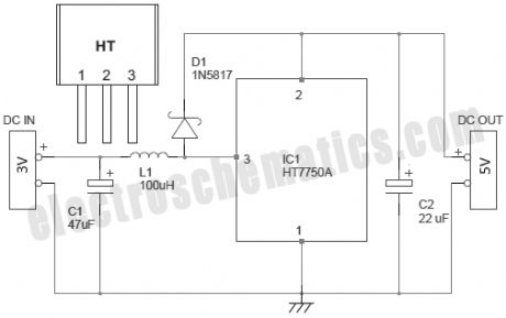
There are several ways to convert an AC voltage at a wall receptacle into the DC voltage required by a microcontroller. Traditionally, this has been done with a transformer and rectifier. However, in applications that involve providing a DC voltage to only the microcontroller and a few other low-current devices, transformer-based power supplies may not be cost effective.
Presented here is the simple circuit of one boost converter, which can output steady 5VDC supply from a 3VDC input. This circuit can be used to power your 5V microcontroller/similar circuits from two standard AA cells (1.5V x2).
(View)
View full Circuit Diagram | Comments | Reading(1110)
Battery Reverse Polarity Protection in LV Applications
Published:2013/8/20 23:03:00 Author:lynne | Keyword: Battery Reverse Polarity Protection in LV Applications
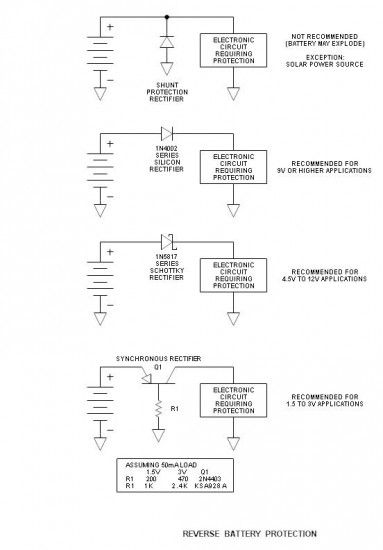
Accidentally connecting a battery reverse can be a real killer in electronic circuits. There are a number of ways to provide protection and all have the expected advantages and disadvantages. Any protection device connected in series with the battery reduces its voltage, and when the battery voltage is only in the order of 1.5 or 3V, every lost millivolt is significant. The highlight of this article is the use of a very low loss active or synchronous rectifier in low voltage applications. (View)
View full Circuit Diagram | Comments | Reading(1087)
Extended Period 555 On-Pulse Timer
Published:2013/8/20 23:01:00 Author:lynne | Keyword: Extended Period 555 On-Pulse Timer
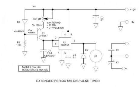
Long and longer timeout periods are frequent goals for the ubiquitous 555 timer. Generally, this is accomplished (albeit unreliably) by unusually large electrolytic timing capacitors. However, here the long period is accomplished by a more predictable ceramic or film capacitor and substantially reduced charging current. The reduced current is generated via a transistor regulated current source, and this current is also easily adjusted. I believe that this low current source trick is new to the world.
(View)
View full Circuit Diagram | Comments | Reading(1002)
MCP73826 500mA Lithium-Ion Battery Charger
Published:2013/8/20 22:59:00 Author:lynne | Keyword: MCP73826 500mA Lithium-Ion Battery Charger

Here is presented a simple 500mA 4.1V or 4.2V Li-ion battery charger that is constructed with the MCP73826 linear charge management controller. There are two versions of this controller MCP73826-4.1 that is preset to a regulation voltage of 4.1V and MCP73826-4.2 with a preset of 4.2V.The IC operates with input voltage between 4.5V to 5.5V. Typical applications are:
single cell Lithium-Ion battery chargers
personal data assistants
cellular telephones
hand held instruments
cradle chargers
digital cameras
(View)
View full Circuit Diagram | Comments | Reading(1200)
ADP1649 1A LED Flash Driver
Published:2013/8/20 3:39:00 Author:lynne | Keyword: ADP1649 1A LED Flash Driver
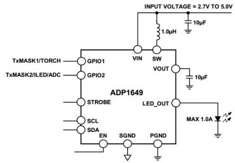
The ADP1649 is a very compact, highly efficient, single white LED flash driver for high resolution camera phones that improves picture and video quality in low light environments. The LED driver maximizes efficiency over the entire battery voltage range to maximize the input power-to-LED power conversion and to minimize battery current draw during flash events.ADP1649 applications
camera enabled cellular phones and smart phones
digital still cameras, camcorders, and PDAs
(View)
View full Circuit Diagram | Comments | Reading(921)
3A 6V/12V Solar Charge Control
Published:2013/8/20 3:12:00 Author:lynne | Keyword: 3A 6V/12V Solar Charge Control
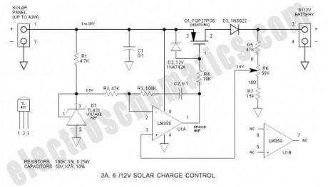
This solar charge control combines multiple features into a single design: 3A current rating, low dropout voltage (LDO), range of voltage adjustment (accommodates 6 & 12V lead-acid batteries), reverse polarity protection, low parts cost ($5.90) and low parts count (14 components). High performance is attributed to the application of the common LM358 op amp and TL431 adjustable shunt voltage regulator.
Specifications
Max solar panel rating (12V): 43W (open circuit solar panel voltage = 18 to 20V)
Max solar panel rating (6V): 22W (open circuit solar panel voltage = 9 to 10V)
Maximum input voltage: 36V
Output voltage range: 4.5 to 15V (continuously adjustable)
Max power dissipation: 17W (includes power dissipation of D3)
Typical dropout voltage: 0.7V @ 3A (less @ lower currents)
Maximum current: 3A (current limiting provided by solar panel characteristics)
Voltage regulation: 5mV (voltage change no load to full load)
Battery discharge: 100µA (most commercially units discharge at typically 5mA)
Reverse battery protection: Control shuts down if battery is inadvertently connected reverse
(View)
View full Circuit Diagram | Comments | Reading(2167)
555 Ignition Coil Driver
Published:2013/8/20 3:08:00 Author:lynne | Keyword: 555 Ignition Coil Driver

This ignition coil driver is a HOT one! From my recollection, it delivers a nastier spark than the legendary Ford Model T ignition coil. The circuit uses an inverted 555 oscillator that is coupled to an ON Semiconductor BU323Z Darlington transistor (350V, 10A) that drives a conventional inductive discharge ignition coil. In this topology, the inductive discharge voltage developed across the transformer primary is multiplied by the turns ration (factor of 100) to easily deliver a 25kV voltage to the spark gap. (View)
View full Circuit Diagram | Comments | Reading(3675)
Troubleshooting Automotive Ignition Systems
Published:2013/8/19 0:55:00 Author:lynne | Keyword: Troubleshooting Automotive Ignition Systems
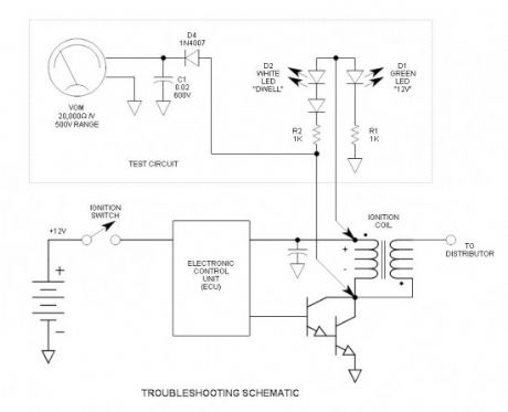
Automobile ignition systems have never been more reliable, but when not, how does one troubleshoot? and is it really an ignition issue? This simple test setup costs only about $1 and may easily be taken for a road test to help isolate mind-blowing intermittent problems. It consists of 2 LEDs and a meter. The standard means of troubleshooting is for a mechanic to change boxes and pass the cost onto the owner even if it does not solve the problem—and some systems have multiple boxes—and it might not even be a box issue. This method will help isolate the problem before making large expenditures.
When my car (86 Dodge Aries) developed intermittent problems, I took it to my mechanic. It ran perfectly while he checked it out. His response: “If it ain’t broke, I can’t fix it.” So I kept driving it until it stalled in pouring rain. I then pulled the wire from the coil to the distributor and checked for spark and it was DEAD. While that was useful information, it did not come close to isolating the problem. Eventually, it restarted after healing itself for another week.
(View)
View full Circuit Diagram | Comments | Reading(1066)
| Pages:61/2234 At 206162636465666768697071727374757677787980Under 20 |
Circuit Categories
power supply circuit
Amplifier Circuit
Basic Circuit
LED and Light Circuit
Sensor Circuit
Signal Processing
Electrical Equipment Circuit
Control Circuit
Remote Control Circuit
A/D-D/A Converter Circuit
Audio Circuit
Measuring and Test Circuit
Communication Circuit
Computer-Related Circuit
555 Circuit
Automotive Circuit
Repairing Circuit