
Circuit Diagram
Index 62
Simple Touch Light Switch Circuit
Published:2013/8/19 0:53:00 Author:lynne | Keyword: Simple Touch Light Switch Circuit
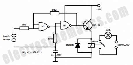
This is a very simple touch light switch circuit that uses the 4011 IC, one transistor and a relay. The C1 capacitor stores the switching state at a certain time and is charged or discharged according to the output signal of N1 gate.When the sensor is touched this state is returned to the input of N1 gate and so there is a change of switching state.
(View)
View full Circuit Diagram | Comments | Reading(1448)
12V to 6V Converter with 7805 or LM309
Published:2013/8/19 0:51:00 Author:lynne | Keyword: 12V to 6V Converter with 7805 or LM309

In this schematic is presented a simple 12 Volts to 6 volts converter circuit that is built with the well-known 7805 voltage regulator or the LM309 IC. You can use 7806 as well, but this circuit comes in handy when you do not have a spare 7806.
You can get out a different voltage, for example 7.5V and in this case you have to use 3 or 4 diodes at the GND pin of the IC. The maximum output current will be 1 amp and you need to use a good heatsink.
The actual voltage might be different, for example using 2 diodes as shown in the schematic can give an output voltage of 6.5V and using one diode will result in a 6V output. It is better to assemble the circuit on a protoboard (breadboard) and test.
(View)
View full Circuit Diagram | Comments | Reading(2769)
Light-Operated Solid State Light Switch
Published:2013/8/15 21:16:00 Author:lynne | Keyword: Light-Operated Solid State Light Switch
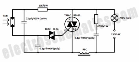
Here is a light-operated light switch circuit built with solid state components that is used to operate a lamp. During darkness the resistance of LDR is in the MΩ range and so the triac does not conduct. When the LDR is illuminated the resistance of the LDR will decrease and the triac will conduct and switched ON the lamp.The LDR must be placed so that is receiving light from the lamp too because this is the way that the lamps remains ON. Once the lamp is ON it can be switched OFF by interrupting the light falling on LDR. The RFC can be made by winding about 15 turns of 18 SWG wire over an insulated ferrite rod.
(View)
View full Circuit Diagram | Comments | Reading(1299)
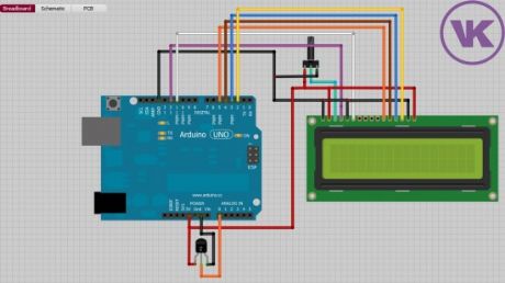
Digital Clock with Arduino and DS1307
Published:2013/8/15 21:12:00 Author:lynne | Keyword: Digital Clock with Arduino and DS1307
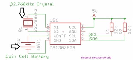
In this article you will learn how to make a digital clock using Arduino and the DS1307 RTC IC. What is DS1307 IC actually? Well, it is a Real Time Clock (RTC) IC that is simple to use, low cost and easy available. The IC basically is able to count the date and time accurately and it will continue its counting if the backup battery – coin cell battery is there although the mainsupply to the IC is cut off.
(View)
View full Circuit Diagram | Comments | Reading(1163)
Fade LED In and Out with Arduino – Tutorial #2
Published:2013/8/15 21:07:00 Author:lynne | Keyword: Fade LED In and Out with Arduino – Tutorial #2

According to how long it stays in 5V and 0V (using the delay() function) you can obtain the fade effect. If delay() has a low value (for example 50ms or 0.05s) the fading speed will be higher because the Arduino will keep the voltage at pin 11 at a certain value only for 50ms then executes the next for() loop.
When the light intensity reaches the highest point then the second for() loop enters in action. This one will decrease the value of the output voltage on pin 11.
(View)
View full Circuit Diagram | Comments | Reading(1825)
Read the State of a Button with Arduino – Tutorial #3
Published:2013/8/14 21:13:00 Author:lynne | Keyword: Read the State of a Button with Arduino , Tutorial #3
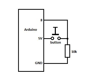
On the first line we set a variable pinButton with an integer value of 8 (the pin number on Arduino Board where we connect the button or switch). Then in the void() function we set the pin 8 as INPUT and initialize the serial port.
In the loop() we declare variable stateButton with the value obtained using the digitalRead() function that reads the state of pin 8. Then it displays its state in the Serial Monitor window as 0 or 1. There is also the delay() that ensures that we can actually read the value. A problem with the delay might be that if you press the button exactly when the delay happens (20ms in our case) then it will display the action in the windows, that why is better to use a lower value or else you might lose some clicks.
(View)
View full Circuit Diagram | Comments | Reading(892)
Turn ON an LED with a Button and Arduino – Tutorial #4
Published:2013/8/14 21:11:00 Author:lynne | Keyword: Turn ON an LED with a Button and Arduino , Tutorial #4
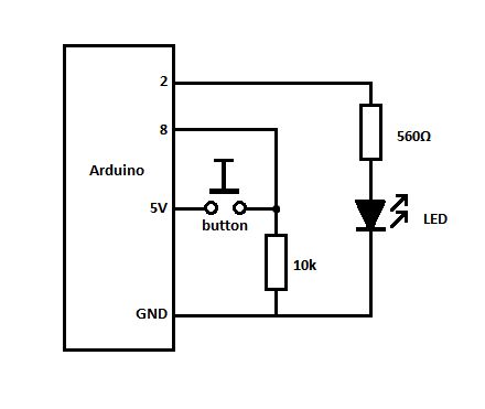
Did you know that you can use Arduino to turn on an LED when you press a button?Well, it is true, you can do this! Leaving the joke aside, let me show how you can achieve this. You will need the Arduino Board, a 560Ω resistor, and LED and the code example below.
(View)
View full Circuit Diagram | Comments | Reading(1126)
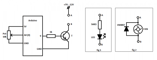
Control a Relay with Arduino – Tutorial #5
Published:2013/8/14 21:03:00 Author:lynne | Keyword: Control a Relay with Arduino , Tutorial #5
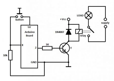
When the button is pressed the Arduino board will put pin 2 in HIGH state, meaning 5V on pin 2. This voltage is used to drive the transistor that will switch ON the relay and the load (in our case the fan) will be powered from the main power supply.
You cannot use the 5V from the USB to power up the transistor and the LOAD because the USB port usually delivers only 100mA, and this is not enough to switch the relay and the LOAD. That is why you must use an external power supply (Vcc) that is between 7 to 12 volts to power up the Arduino board and the transistor + relay. The load uses its own power supply, for instance if you use a light bulb then you might connect it to the 110/220V mains or any other power source.
(View)
View full Circuit Diagram | Comments | Reading(1850)
Temperature Controlled Relay with Arduino – Tutorial #6
Published:2013/8/13 21:31:00 Author:lynne | Keyword: Temperature Controlled Relay with Arduino , Tutorial #6


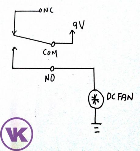
In this project, we are going to build something very simple project, a temperature controlled relay that is used to turn on a dc fan. You can actually change the DC Fan to other electrical devices such as light or servo motor. We are going to make an automatic fan that will be ON when the temperature rises above certain threshold temperature and OFF when it is below.
(View)
View full Circuit Diagram | Comments | Reading(1520)
The LED Brightness or Fan Speed with Arduino – Tutorial #7
Published:2013/8/13 21:27:00 Author:lynne | Keyword: The LED Brightness or Fan Speed with Arduino , Tutorial #7
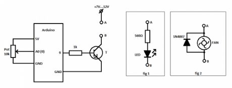
We set the potentiometer pin as 0 (A0 on the Arduino Uno board), the CONTROL variable is the voltage that is used to cotrol the led brightness of the speed of the fan. In the setup() function the CONTROL pin 9 is set as OUTPUT. In the loop() we are getting the analog reading value of the voltage that is applied on pin A0 or 0.
Then use the map() function to translate the value 1024 to 255 and store it in the value variable. After that Arduino writes this value to the CONTROL pin, resulting in a variable voltage that is dependent on the pontetiometer value (its voltage on the adjustable pin, in this case it is connected as a voltage divider *see the schematic).
 (View)
View full Circuit Diagram | Comments | Reading(1205)
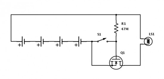
Battery Capacity, Discharge and Load Testing
Published:2013/8/13 21:24:00 Author:lynne | Keyword: Battery Capacity, Discharge and Load Testing

This project is cool because it features the re-use of found objects in electronics; things you might have laying around the garage, or at a yard sale, and thrift stores often have bins of this type of simple gear. It also is an easy tool for learning about battery discharge curves, loads, resistance, and testing capacity of different batteries.This is a simple and inexpensive battery testing setup, best for comparing different batteries capacities, or load testing to check the state of charge. If you calculate the current in this circuit and use the clock to measure the time it takes to discharge the battery you can get a good measure of the capacity of the battery.
This type of device is good for testing different brands or types of batteries, to compare them, or to determine which best needs your needs. You can figure out the cost per mah, and take DMM readings to get a discharge voltage curve to see how the cells hold or lose voltage under load.
This type of information is great for learning about characteristics of batteries in general, and how different chemistries of batteries act under load, which will be invaluable for deciding the size, type and chemistry for your future projects.
(View)
View full Circuit Diagram | Comments | Reading(1553)
Infrared Beam Break Detector
Published:2013/8/13 4:06:00 Author:lynne | Keyword: Infrared Beam Break Detector
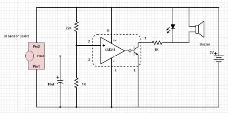
The IR sensor responds to pulsed infrared, not ambient or continuous IR. This means that another transmitter project is necessary in order to complete this one! Note though that some forms of lighting like fluorescent lighting may interfere with the sensor. For convenience, the the buzzer is internally driven so that a only Vdc is needed to make a sound. In this case, the IR sensor senses 38kHz pulsed infrared light.
Pin 3 of the IR sensor is actually low (0V) while receiving a signal. When the sensor is blocked from receiving the IR signal, the sensor outputs a high signal to the comparator, which then allows current through the LED/Buzzer circuit, and alerting you that the beam is broken. In the Scheme-It drawing the LM311 IC is a grouping of three components, in a functional block diagram style, to show how it functions in the circuit beyond what the pinouts would show normally.
(View)
View full Circuit Diagram | Comments | Reading(928)
Lightning Strike Detection
Published:2013/8/13 4:05:00 Author:lynne | Keyword: Lightning Strike Detection

It picks up and amplifies signals in the 300 kHz range, where lightning makes a lot of noise that can be picked up with a radio. The antenna and receiver are tuned to 300 kHz, with the receiver’s output connected to an amplifier that drives the lamp flashing circuitry, alerting you to lightning in the area.Use the potentiometer to reduce the sensitivity to noise and still be able to detect lightning strikes. In addition to lightning, this will also respond to noise from motors inside appliances like refrigerators, washers, and air-conditioners. Another easy way to affect the sensitivity is to take off the antenna, or lengthen it depending on the conditions. To get some confirmation while tuning the detector, you can tune an AM radio to the bottom the of the dial as well.
You can use it to track weather, and be prepared for it. It is small enough and can be placed in a project box or waterproof container to use, on a boat for instance. The lamp can be replaced or even used alongside a buzzer to give an audible alert as well, so that constant monitoring is not necessary.
(View)
View full Circuit Diagram | Comments | Reading(1320)
LA4440 Audio Amplifier
Published:2013/8/13 3:58:00 Author:lynne | Keyword: LA4440 Audio Amplifier

A simple audio amplifier based on the LA4440 IC. This will take your computer’s headphone level output and amplify it to drive a pair of external speakers. If you are listening to music or movies on laptops and computers, this is a useful little project for you. Laptop speakers are never loud enough to give satisfying listening. They give users the ability to hear something, but for anything like music or movie soundtracks they are very poor performers. The output from a laptops built in speakers is just too low, and this circuit addresses that low power with some additional amplification.
This circuit uses an LA4440 and some supporting components to give you much more power, while retaining a small package that you can use. The IC is a dual channel audio power amplifier, with low distortion, and a good frequency range.
Using 2 channels, the LA4440 will output 6 watts per channel, that can drive much larger speakers than a laptop can hold. When you set up a small enclosure(s), a 12V power supply, and an audio jack connection to the laptop you’ll have a nice enhancement to your laptop audio enjoyment.
(View)
View full Circuit Diagram | Comments | Reading(1874)
AM Receiver Circuit
Published:2013/8/12 4:57:00 Author:lynne | Keyword: AM Receiver Circuit

It can use general purpose transistors, and in this example there are 3 BC109C transistors. The schematic and BOM show a 200µH inductor and a trimmer capacitor 150-500pF, though these parts can be salvaged from an old AM radio, to preserve the directional nature of a tuning coil, and an adjustment knob (plate capacitor) that work well for radio reception.
The 120k resistor is for regenerative feedback between the Q2 NPN transistor and the input to the tank circuit. The value of this resistor is important to the performance of the entire AM receiver. In fact, it may be better to replace the fixed value with a variable resistor paired with a fixed resistor to adjust the oscillation and sensitivity. All the connections should be short to minimize interference.
Performance will vary depending on stray capacitance in your layout, the inductor winding/core/length, etc. Changing values of some of the capacitors, or adding them, as well as a potentiometer in the feedback loop can help with the performance of the receiver. With such a small circuit that is affected so much by its construction and its environment, a lot of hand tuning and experimentation will be fun, instructive, and possibly necessary to make it work best.
(View)
View full Circuit Diagram | Comments | Reading(1757)
Network Cable Tester
Published:2013/8/12 4:55:00 Author:lynne | Keyword: Network Cable Tester
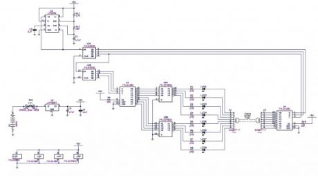
This network cable tester is designed for testing network cable with CAT 5 connectors, RJ-45. It can be modified to test any 8 conductor cable by replacing the RJ-45 jacks with the mating connectors of the cable to be tested.
(View)
View full Circuit Diagram | Comments | Reading(1413)
Soft Start for Flashlights
Published:2013/8/12 4:53:00 Author:lynne | Keyword: Soft Start for Flashlights

Application:
A project with only 2 parts, but is great for addressing an everyday situation that is irritating at best and dangerous at worst. This circuit protects the bulb in flashlights (FL) from high switch-on current to make the bulb last longer.Description:
For a standard incandescent flashlight (FL), this is a easy little modification make your FL bulbs last longer. High powered FLs typically run their bulbs hot to get a brighter light from them. They also have a much lower on-resistance when cold, so that when you turn them on, the bulb passes a much higher current than it was designed for. This is why the most common time for a bulb failure is when turning it on.
The transistor and resistor limit the current while turning on the circuit and protect the bulb from an initial high current turn on. A simple resistor in series with the bulb might be a tempting option, but there are a couple problems with that approach. Just adding a resistor would reduce the voltage available to the bulb, and aid longevity, but that would reduce the brightness. The resistor would also be wasting energy getting hot instead of using that energy for light. This solution is better in that it limits current at startup and wastes very little energy when in use and when off.
In this application, it might be easier to insert the batteries in the FL“backwards” so the circuit connections and parts have the best fit in the body of the FL. FL design was stagnant for decades, but now there are many new technologies available, and in some cases, it can even be easy to bring some of them to an older one you already have. In addition to this circuit, you could also take advantage of newer LED and battery technology to really increase the brightness, “on” time, and lamp life of your old FL.
 (View)
View full Circuit Diagram | Comments | Reading(982)
Long Duration Timer
Published:2013/8/8 20:22:00 Author:lynne | Keyword: Long Duration Timer
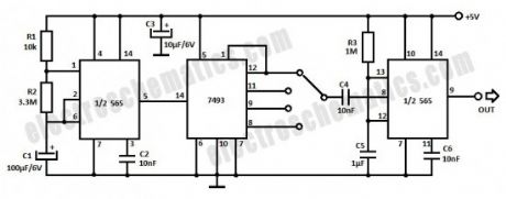
In order to create a long duration timer the 556 IC teamed up with a binary divider can provide delays as much as 16 times that set by the time constant of the first timer. You can use two 555 ICs instead of the 556.The first timer provides a delay of 7.5 minutes and the divided outputs give a delay of 15 min, 30 min, 1 hour and 2 hours respectively. The second timer is used to obtain the desired output pulse length. Additional dividers may be added to give longer delays.
(View)
View full Circuit Diagram | Comments | Reading(996)
Single Transistor Amplifier Revisited – Part 4
Published:2013/8/8 20:20:00 Author:lynne | Keyword: Single Transistor Amplifier Revisited, Part 4

What happens to voltage gain when a bipolar transistor is operated at low voltages (Vce < 1V). In a previous circuit that operated at a quiescent Vce of 0.75V, voltage gain was demonstrably low. This experiment is an attempt to quantify what actually happens to voltage gain and input resistance in a general purpose transistor over the range of Vce = 0.1 to 10V. The results are interesting and informative.
(View)
View full Circuit Diagram | Comments | Reading(1424)
Low Cost Door Sensor
Published:2013/8/8 20:19:00 Author:lynne | Keyword: Low Cost Door Sensor
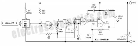
At the heart of the circuit is one Unipolar Hall effect sensor MH183 (HS1). It incorporates advanced chopper stabilization technology to provide accurate and stable magnetic switch points. The internal output transistor of MH183 will be switched on in the presence of a sufficiently strong South pole magnetic field facing the marked side of the package. Similarly, the output will be switched off in the presence of a weaker South field and remain off with “0” field. A Hall-effect sensor IC (contactless & magnetically activated) is more efficient and effective than reed, inductive or opto-electronic sensors, and is virtually immune to environmental contaminants.
(View)
View full Circuit Diagram | Comments | Reading(1915)
| Pages:62/2234 At 206162636465666768697071727374757677787980Under 20 |
Circuit Categories
power supply circuit
Amplifier Circuit
Basic Circuit
LED and Light Circuit
Sensor Circuit
Signal Processing
Electrical Equipment Circuit
Control Circuit
Remote Control Circuit
A/D-D/A Converter Circuit
Audio Circuit
Measuring and Test Circuit
Communication Circuit
Computer-Related Circuit
555 Circuit
Automotive Circuit
Repairing Circuit