
Circuit Diagram
Index 63
AC Power Line Hi/Lo Voltage Tester
Published:2013/8/7 20:59:00 Author:lynne | Keyword: AC Power Line Hi/Lo Voltage Tester
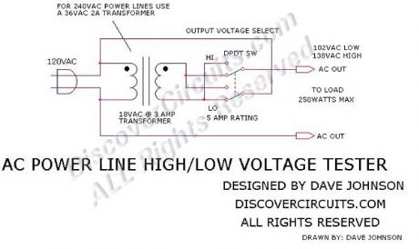
If you wish to test a line-powered device under both a 15% high and a 15% low voltage condition, you can use the circuit below. The circuit uses an 18v transformer with a 3 amp rating. A double pole, double throw toggle switch then switches in the transformer voltage in either a buck or a boost mode. In the buck mode, the transformer voltage is subtracted from the line voltage. In the boost mode, the transformer voltage is added to the line voltage. With an 18vac transformer the normal 120vac voltage is switched between 102vac and 138vac. For 240vac power line tests, use a 36vac transformer rated at 2A.
(View)
View full Circuit Diagram | Comments | Reading(1414)
AC Line Under/Over Voltage Alarm Circuit
Published:2013/8/7 20:57:00 Author:lynne | Keyword: AC Line Under/Over Voltage Alarm Circuit


Power lines, which deviate much beyond normal voltages can damage expensive electronic equipment. The circuit below sounds an alarm whenever the line voltage is higher or lower than normal. I set the alarm limits at about +-15% from standard levels. The circuit rectifies and filters the power line signal. I set the resistor values, so the DC voltage produced is close to 1% of the RMS value of the line. Thus, a 120vac line would yield about 1.2v DC. That voltage is fed to a pair of voltage comparators.
The outputs of the comparators decide if the sampled voltage is above, below or acceptable. Three LEDs indicate the voltage range. A green LED is lit if the voltage is OK. If the voltage is outside normal levels, the circuit sounds an alarm using a small magnet or piezoelectric beeper. I have shown recommended resistor values for both 120vac and 240vac power lines.
(View)
View full Circuit Diagram | Comments | Reading(1514)
SOLID STATE RELAY REQUIRES ONLY 50uA DRIVE CURRENT CIRCUIT
Published:2013/8/7 20:53:00 Author:lynne | Keyword: SOLID STATE RELAY REQUIRES ONLY 50uA DRIVE CURRENT CIRCUIT
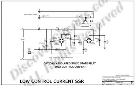
Most solid state relays require at least 5ma and often more input control current, to fully turn on the device. But such current levels often force battery powered circuits to use excessively large batteries. The relay hobby circuit shown below demands only 50uA of input current. This about 100 times lower than that needed by a typical optically isolated solid state relays. The circuit uses a combination of a high current triac and a very sensitive low current SCR, to control up to 600 watts of power to a load, while providing full isolation and transient protection.
[H-Corner/ads/i-HC-boombox.htm]
At the heart of the circuit is a Darlington type opto-isolator A1 from NEC. This device needs only 50uA of current through the LED section to activate the Darlington side. A bridge rectifier and a couple capacitors, strips off a bit of current from the 120vac line, through the load. A zener diode limits the generated DC voltage to 8v. When the opto-isolator is turned on, current is routed to the gate of a sensitive SCR. When turned on, the SCR routes current pulses to the main control triac, through a bridge rectifier. A 15v zener delays the trigger point of the triac slightly, so a minimum 30 volts peak to peak is always available to maintain current to the SCR circuit.
(View)
View full Circuit Diagram | Comments | Reading(1204)
POLICE SIREN
Published:2013/8/5 20:44:00 Author:lynne | Keyword: POLICE SIREN

The Police Siren circuit uses two 555's to produce an up-down wailing sound. The first 555 is wired as a low-frequency oscillator to control the VOLTAGE CONTROL pin 5 of the second 555. The voltage shift on pin 5 causes the frequency of the second oscillator to rise and fall.
(View)
View full Circuit Diagram | Comments | Reading(1979)
RAIN ALARM
Published:2013/8/5 20:42:00 Author:lynne | Keyword: RAIN ALARM

This circuit consumes no current until moisture is detected on the rain plate.
(View)
View full Circuit Diagram | Comments | Reading(0)
REACTION TIMER GAME
Published:2013/8/5 20:09:00 Author:lynne | Keyword: REACTION TIMER GAME

This is a game for two players. Player 1 presses the START button. This resets the 4026 counter chip and starts the 555 oscillator. The 555 produces 10 pulses per second and these are counted by the 4026 chip and displayed on the 7-Segment display. The second player is required to press the STOP button. This freezes the display by activating the Clock Inhibit line of the 4026 (pin 2).Two time-delay circuits are included. The first activates the 555 by charging a 10u electrolytic and at the same time delivering a (high) pulse to the 4026 chip to reset it. The second timer freezes the count on the display (by raising the voltage on pin 2) so it can be read.
(View)
View full Circuit Diagram | Comments | Reading(2430)
ROULETTE
Published:2013/8/5 5:39:00 Author:lynne | Keyword: ROULETTE
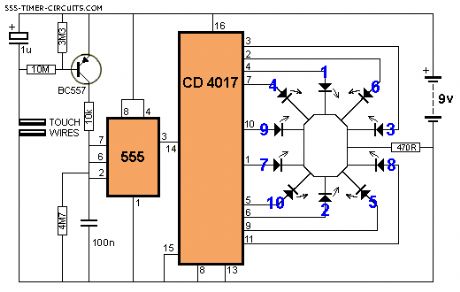
This circuit creates a rotating LED that starts very fast when a finger touches the TOUCH WIRES. When the finger is removed, the rotation slows down and finally stops. (View)
View full Circuit Diagram | Comments | Reading(1104)
SCREAMER
Published:2013/8/5 5:38:00 Author:lynne | Keyword: SCREAMER

This circuit will produce an ear-piercing scream, depending on the amount of light being detected by the Light Dependent Resistor.
(View)
View full Circuit Diagram | Comments | Reading(924)
SCREAMER circuit
Published:2013/8/5 5:37:00 Author:lynne | Keyword: SCREAMER circuit

This circuit will produce an ear-piercing scream, depending on the amount of light being detected by the Light Dependent Resistor.
(View)
View full Circuit Diagram | Comments | Reading(929)
SERVO TESTER
Published:2013/8/5 5:35:00 Author:lynne | Keyword: SERVO TESTER

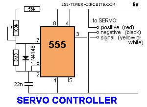
This circuit can be used to manually turn a servo clockwise and anti-clockwise. By pushing the forward or reverse button for a short period of time you can control the rotation of the servo. It will also test a servo. Here is a photo of a kit from Cana Kit for $10.00 plus postage (it is a slightly different circuit) and a motor and gearbox, commonly called a servo. The output shaft has a disk or wheel containing holes. A linkage or push-rod is fitted to a hole and when the disk rotates, the shaft is pushed and pulled. The shaft only rotates about 180� to actuate flaps or ailerons etc.
A pot can be used to control the position of the servo by using the following circuit. It produces a positive pulse between about 0.9 milliseconds and 2.1 milliseconds. The off period between pulses is about 40 milliseconds. This can be shortened by reducing the value of the 3M3 resistor. (View)
View full Circuit Diagram | Comments | Reading(1215)
SIREN 100dB
Published:2013/8/1 22:42:00 Author:lynne | Keyword: SIREN 100dB
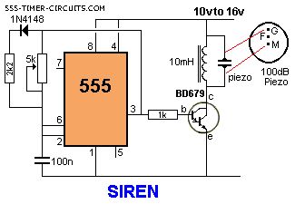
This is a very loud siren and if two or more piezo's are located in a room, the burglar does not know where the sound is coming from. A robber will not stay anywhere with an ear-piercing sound as he cannot hear if someone is approaching. It's the best deterrent you can get. The F contact on the piezo is feedback and is not needed in this circuit.
(View)
View full Circuit Diagram | Comments | Reading(1290)
TILT SWITCH
Published:2013/8/1 22:27:00 Author:lynne | Keyword: TILT SWITCH
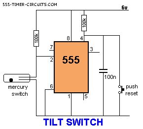
The output is LOW at start-up due to the capacitor on pin 4. When the mercury switch closes, the output goes HIGH and remains HIGH until the reset button is pressed. This circuit is called a LATCH. (View)
View full Circuit Diagram | Comments | Reading(1090)
TOUCH SWITCH and TOUCH ON-OFF
Published:2013/8/1 22:25:00 Author:lynne | Keyword: TOUCH SWITCH and TOUCH ON-OFF

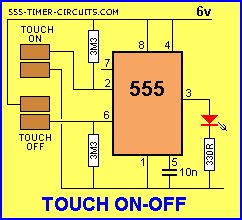

The Touch Switch circuit will detect stray voltages produced by mains voltages and electrostatic build-up in a room. In the first circuit, pin 2 must see a LOW for the circuit to activate. If sufficient static voltage is detected by the plate, the chip will change state. If not, you will need to touch the plate and the 0v rail. In the second circuit, two touch plates are provided and the resistance of your finger changes the voltage on pin 2 or 6 to toggle the 555.
The circuit can be made 100 times more sensitive by adding a transistor to the front-end as shown in the diagram below:
(View)
View full Circuit Diagram | Comments | Reading(2839)
TOY ORGAN
Published:2013/8/1 4:50:00 Author:lynne | Keyword: TOY ORGAN

This circuit produces a tone according to the button being pressed. Only 1 button can be pressed at a time, that's why it is called a monophonic organ. You can change the 1k resistors to produce a more-accurate scale. (View)
View full Circuit Diagram | Comments | Reading(1372)
TRAFFIC LIGHTS
Published:2013/8/1 4:47:00 Author:lynne | Keyword: TRAFFIC LIGHTS
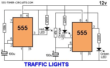
Here's a clever circuit using two 555's to produce a set of traffic lights for a model layout. The animation shows the lighting sequence and this follows the Australian-standard. The red LED has an equal on-off period and when it is off, the first 555 delivers power to the second 555. This illuminates the Green LED and then the second 555 changes state to turn off the Green LED and turn on the Orange LED for a short period of time before the first 555 changes state to turn off the second 555 and turn on the red LED. A supply voltage of 9v to 12v is needed because the second 555 receives a supply of about 2v less than rail. This circuit also shows how to connect LEDs high and low to a 555 and also turn off the 555 by controlling the supply to pin 8. Connecting the LEDs high and low to pin 3 will not work and since pin 7 is in phase with pin 3, it can be used to advantage in this design. (View)
View full Circuit Diagram | Comments | Reading(1443)
TV REMOTE CONTROL JAMMER
Published:2013/8/1 4:45:00 Author:lynne | Keyword: TV REMOTE CONTROL JAMMER
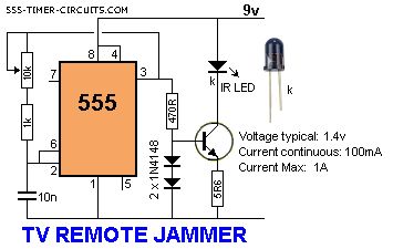
This circuit confuses the infra-red receiver in a TV. It produces a constant signal that interferes with the signal from a remote control and prevents the TV detecting a channel-change or any other command. This allows you to watch your own program without anyone changing the channel !! The circuit is adjusted to produce a 38kHz signal. The IR diode is called an Infra-red transmitting Diode or IR emitter diode to distinguish it from a receiving diode, called an IR receiver or IR receiving diode. (A Photo diode is a receiving diode). There are so many IR emitters that we cannot put a generic number on the circuit to represent the type of diode. Some types include: CY85G, LD271, CQY37N (45�), INF3850, INF3880, INF3940 (30�). The current through the IR LED is limited to 100mA by the inclusion of the two 1N4148 diodes, as these form a constant-current arrangement when combined with the transistor and 5R6 resistor. (View)
View full Circuit Diagram | Comments | Reading(833)
Photo Timer Circuit
Published:2013/7/30 20:46:00 Author:muriel | Keyword: Photo Timer Circuit

Time is set by potentiometer R2 which provides a range or 1 sec. To 100 seconds with timing capacitor C1 of 100uF. The output at pin 3 is normally low and the relay is held off. A momentary push on switch S1 energies the relay which is held closed for a time 1.1 X (R1+R2). C1 and then released. The exact length of the timing interval will depend on the actual capacitance of C1. Most electrolytic capacitors are rated on the basis of minimum guaranteed value and the actual value may be higher. The circuit should be calibrated for various positions of the control knob of R2 after the timing capacitor has had a chance to age. Once the capacitor has reached its stable value, the timings provided should be well within the photographic requirements.
PartsC1 - 100uF, 25V electrolyticC2 - 0.01uF, disc ceramicD1, D2 - DR50 or 1N4001R!,R2 - 10K ohms, ¼ wattsR3 - 1 M ohms, potentiometerRLY1 - 12V, DC relay, operating current less than 200mAS1 - Push-to-on switchU1 - NE555 timer ICP1 & P2 are for exposure lamp ckt. (View)
View full Circuit Diagram | Comments | Reading(920)
Amplifier Timers
Published:2013/7/30 20:45:00 Author:muriel | Keyword: Amplifier Timers
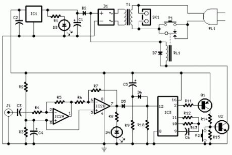
Parts:R1,R8 1K 1/4W ResistorsR2,R3 4K7 1/4W ResistorsR4 22K 1/4W ResistorR5 4M7 1/4W ResistorR6,R9 10K 1/4W ResistorsR7 1M5 1/4W ResistorR10 100K 1/4W ResistorR11 15K 1/4W ResistorR12 10M 1/4W ResistorR13 1M 1/4W ResistorR14 8K2 1/4W ResistorR15 1K8 1/4W ResistorC1 470µF 25V Electrolytic CapacitorC2,C3,C6 100nF 63V Polyester CapacitorsC4,C5 10µF 25V Electrolytic CapacitorsD1 Diode bridge 100V 1A D2,D7 1N4002 100V 1A DiodesD3 Red LED 5mm.D4 Yellow LED 5mm.D5,D6 1N4148 75V 150mA DiodesIC1 78L12 12V 100mA Voltage regulator ICIC2 LM358 Low Power Dual Op-ampIC3 4060 14 stage ripple counter and oscillator ICQ1 BC557 45V 100mA PNP TransistorQ2 BC337 45V 800mA NPN TransistorJ1 RCA audio input socketP1 SPST Mains suited PushbuttonP2 SPST PushbuttonT1 220V Primary, 12V Secondary 3VA Mains transformerRL1 10.5V 270 Ohm Relay with SPST 5A 220V switchPL1 Male Mains plugSK1 Female Mains socket
Circuit operation:This circuit turns-off an amplifier or any other device when a low level audio signal fed to its input is absent for 15 minutes at least.Pushing P1 the device is switched-on feeding any appliance connected to SK1. Input audio signal is boosted and squared by IC2 A & B and monitored by LED D4. When D4 illuminates, albeit for a very short peak, IC3 is reset and restarts its counting. Pin 2 of IC3 remains at the low state, the two transistors are on and the relay operates. When, after a 15 minutes delay, no signal appeared at the input, IC3 ends its counting and pin 2 goes high. Q1 & Q2 stop conducting and the relay switches-off. The device is thus completely off as also are the appliances connected to SK1. C5 & R9 reset IC3 at power-on. P2 allows switch-off at any moment.
Notes:Simply connect left or right channel tape output of your amplifier to J1.You can employ two RCA input sockets wired in parallel to allow pick-up audio signals from both stereo channels.The delay time can be varied changing R13 and/or C6 values.Needing to operate a device not supplied by power mains, use a double pole relay switch, connecting the second pole switch in series with the device's supply. (View)
View full Circuit Diagram | Comments | Reading(813)
1KHz Sinewave Generator
Published:2013/7/30 20:44:00 Author:muriel | Keyword: 1KHz , Sinewave Generator
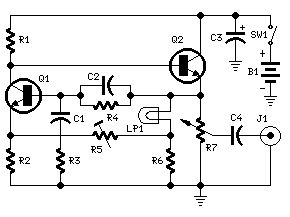
Parts:R1 5K6 1/4W ResistorR2 1K8 1/4W ResistorR3,R4 15K 1/4W ResistorsR5 500R 1/2W Trimmer CermetR6 330R 1/4W ResistorR7 470R Linear PotentiometerC1,C2 10nF 63V Polyester CapacitorsC3 100µF 25V Electrolytic CapacitorC4 470nF 63V Polyester CapacitorQ1,Q2 BC238 25V 100mA NPN TransistorsLP1 12V 40mA Lamp (See Notes)J1 Phono chassis SocketSW1 SPST Slider SwitchB1 9V PP3Clip for 9V PP3 Battery
Circuit description:This circuit generates a good 1KHz sinewave using the inverted Wien bridge configuration (C1-R3 & C2-R4). Features a variable output, low distortion and low output impedance in order to obtain good overload capability. A small filament lamp ensures a stable long term output amplitude waveform. Useful to test the Audio Millivoltmeter, Audio Power Meter and other audio circuits published in this site.
Notes:The lamp must be a low current type (12V 40-50mA or 6V 50mA) in order to obtain good long term stability and low distortion.Distortion @ 1V RMS output is 0.15% with a 12V 40mA lamp, raising to 0.5% with a 12V 100mA one.Using a lamp differing from specifications may require a change in R6 value to 220 or 150 Ohms to ensure proper circuit's oscillation.Set R5 to read 1V RMS on an Audio Millivoltmeter connected to the output with R7 fully clockwise, or to view a sinewave of 2.828V Peak-to-Peak on the oscilloscope.With C1,C2 = 100nF the frequency generated is 100Hz and with C1,C2 = 1nF frequency is 10KHz but R5 is needing adjustment.High gain transistors preferred for better performance. (View)
View full Circuit Diagram | Comments | Reading(1125)
Timed Beepers
Published:2013/7/30 20:44:00 Author:muriel | Keyword: Timed Beepers
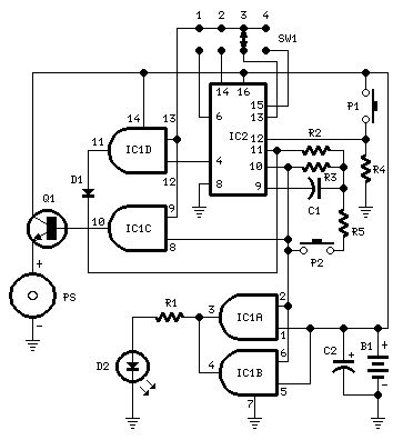
Beeps 7.5 seconds after a preset timeAdjustable time settings: 15 sec. 30 sec. 1 min. 2 min. & others
Parts:R1 220R 1/4W ResistorR2 10M 1/4W ResistorR3 1M 1/4W ResistorR4 10K 1/4W ResistorR5 47K 1/4W ResistorC1 100nF 63V Polyester CapacitorC2 22µF 25V Electrolytic CapacitorD1 1N4148 75V 150mA DiodeD2 3mm. Red LEDIC1 4081 Quad 2 input AND Gate ICIC2 4060 14 stage ripple counter and oscillator ICQ1 BC337 45V 800mA NPN TransistorP1 SPST Pushbutton (Start)P2 SPST Pushbutton (Reset)SW1 4 ways Switch (See notes)PS Piezo sounder (incorporating 3KHz oscillator)B1 3V Battery (2 AA 1.5V Cells in series)
Device purpose:This circuit is intended for alerting purposes after a certain time is elapsed. It is suitable for table games requiring a fixed time to answer a question, or to move a piece etc. In this view it's a modern substitute for the old sandglass. Useful also for time control when children are brushing teeth (at least two minutes!), or in the kitchen, and so on.
Circuit operation:Pushing P1 resets IC2 that start oscillating at a frequency fixed by R3 & C1. With values shown, this frequency is approx. 4Hz. The LED D2, driven by IC1A & B, flashing at the same oscillator frequency, signals proper circuit operation. SW1 selects the appropriate pin of IC2 thus adjusting timing duration:Position 1 = 15 secondsPosition 2 = 30 secondsPosition 3 = 1 minutePosition 4 = 2 minutes When the selected pin of IC2 goes high, IC1C drives Q1 and the piezo sounder beeps intermittently at the same frequency of the LED. After approx. 7.5 seconds pin 4 of IC2 goes high and IC1D stops the oscillator through D1. If you want to stop counting in advance, push P2.
Notes:SW1 can be any type of switch with the desired number of ways. If you want a single fixed timing duration, omit the switch and connect pins 9 & 13 of IC1 to the suitable pin of IC2.The circuit's reset is not immediate. Pushing P2 forces IC2 to oscillate very fast, but it takes some seconds to terminate the counting, especially if higher timer's duration is chosen and the pushbutton is operated when the circuit has just started. In order to speed the reset, try lowering the value of R5, but pay attention: too low a value can stop oscillation.Frequency operation varies with different brand names for IC2. E.g. Motorola's ICs run faster, therefore changing of C1 and/or R3 values may be necessary.You can also use pins 1, 2, 3 of IC2 to obtain timings of 8, 16 and 32 minutes respectively.An on-off switch is not provided because in the off state the circuit draws no significant current. (View)
View full Circuit Diagram | Comments | Reading(1117)
| Pages:63/2234 At 206162636465666768697071727374757677787980Under 20 |
Circuit Categories
power supply circuit
Amplifier Circuit
Basic Circuit
LED and Light Circuit
Sensor Circuit
Signal Processing
Electrical Equipment Circuit
Control Circuit
Remote Control Circuit
A/D-D/A Converter Circuit
Audio Circuit
Measuring and Test Circuit
Communication Circuit
Computer-Related Circuit
555 Circuit
Automotive Circuit
Repairing Circuit