
Circuit Diagram
Index 79
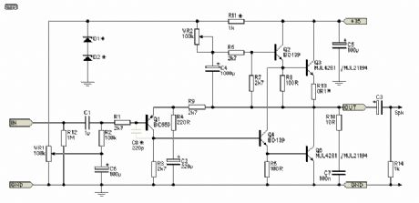
DoZ Headphone Amplifier
Published:2013/7/9 3:21:00 Author:muriel | Keyword: DoZ Headphone Amplifier
View full Circuit Diagram | Comments | Reading(1573)
CMoy Headphone Amplifier
Published:2013/7/9 3:21:00 Author:muriel | Keyword: CMoy Headphone Amplifier
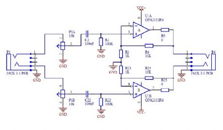

CMoy is very simple portable headphone amplifier. The amplifier was originally posted by Chu Moy on headwize.com. The best source of information about this amplifier is article How to Build the CMoy Pocket Amplifier. If you use Google, you will find many pages and pictures about CMoy. Few months ago I decided built this amplifier also. In my post you can find my experience with creating this simple but very good amplifier. (View)
View full Circuit Diagram | Comments | Reading(3948)
corner of PCB
Published:2013/7/9 3:18:00 Author:muriel | Keyword: corner of PCB

View full Circuit Diagram | Comments | Reading(713)
ISP
Published:2013/7/9 3:18:00 Author:muriel | Keyword: ISP

View full Circuit Diagram | Comments | Reading(1125)
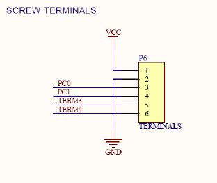
Screw terminals
Published:2013/7/9 3:17:00 Author:muriel | Keyword: Screw terminals
View full Circuit Diagram | Comments | Reading(839)
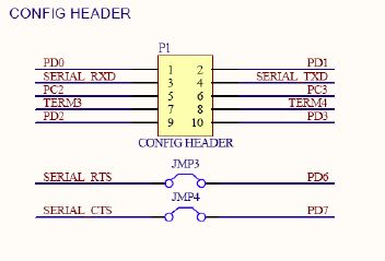
Config header
Published:2013/7/9 3:17:00 Author:muriel | Keyword: Config header
View full Circuit Diagram | Comments | Reading(712)
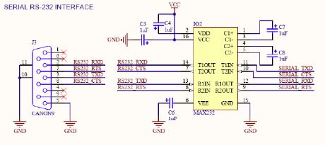
Standard serial interface
Published:2013/7/9 3:17:00 Author:muriel | Keyword: Standard serial interface
View full Circuit Diagram | Comments | Reading(1162)
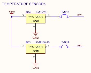
temperature sensors
Published:2013/7/9 3:17:00 Author:muriel | Keyword: temperature sensors
View full Circuit Diagram | Comments | Reading(1183)
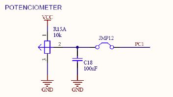
potenciometer
Published:2013/7/9 3:16:00 Author:muriel | Keyword: potenciometer
View full Circuit Diagram | Comments | Reading(746)
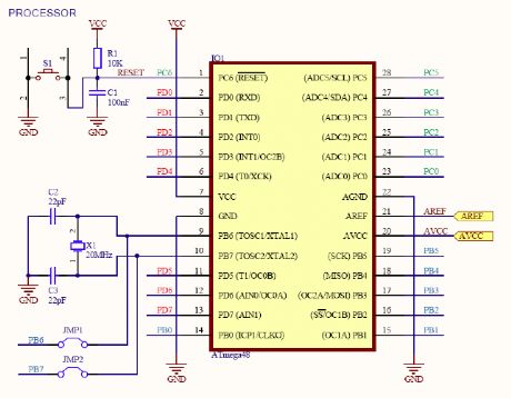
The microcontroller
Published:2013/7/9 3:16:00 Author:muriel | Keyword: The microcontroller
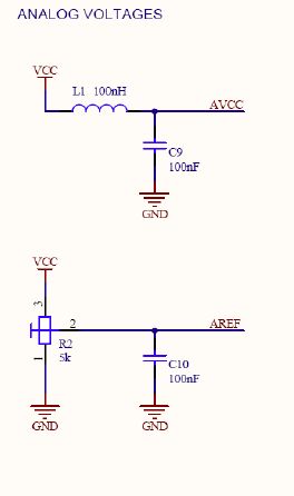
The microcontroller has built-in 10bits AD converter. On the board is LC filter for power supply of this ADC. You can use internal or external reference. The rotary trimming resistor R2 is connected to Aref input for playing with the external reference. (View)
View full Circuit Diagram | Comments | Reading(1470)
Piezo speakers
Published:2013/7/9 3:15:00 Author:muriel | Keyword: Piezo speaker

View full Circuit Diagram | Comments | Reading(997)
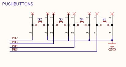
Four buttons
Published:2013/7/9 3:15:00 Author:muriel | Keyword: Four buttons
View full Circuit Diagram | Comments | Reading(707)
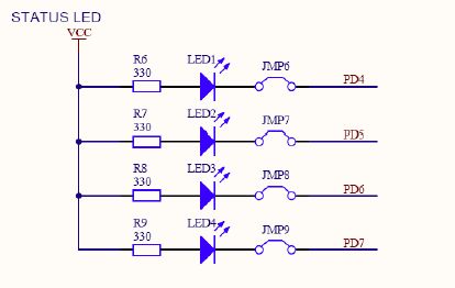
status LED
Published:2013/7/9 3:14:00 Author:muriel | Keyword: status LED
View full Circuit Diagram | Comments | Reading(1071)
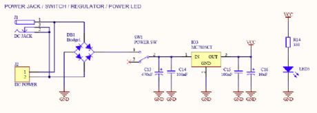
power jack/switch/regulator/power LED
Published:2013/7/9 3:14:00 Author:muriel | Keyword: power jack, switch, regulator, power LED
View full Circuit Diagram | Comments | Reading(1676)
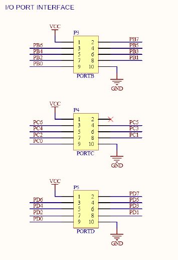
I/O port interface
Published:2013/7/9 3:13:00 Author:muriel | Keyword: I/O port interface
View full Circuit Diagram | Comments | Reading(731)
headphone jack sensing design
Published:2013/7/9 3:13:00 Author:muriel | Keyword: headphone jack sensing design
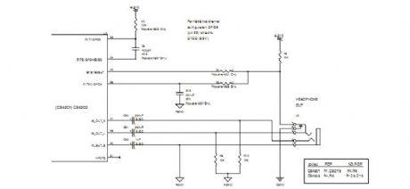
View full Circuit Diagram | Comments | Reading(1825)
ATmega48/88/168 Development Board
Published:2013/7/9 3:12:00 Author:muriel | Keyword: ATmega48/88/168 Development Board
View full Circuit Diagram | Comments | Reading(1066)
Wilf Bridge-Head
Published:2013/7/9 3:11:00 Author:muriel | Keyword: Wilf Bridge-Head

View full Circuit Diagram | Comments | Reading(808)
DC-DC converter 2
Published:2013/7/9 3:10:00 Author:muriel | Keyword: DC-DC converter
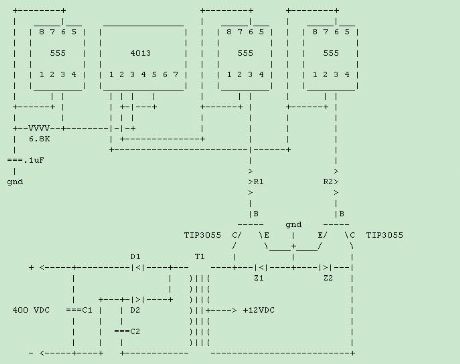
This DC-DC converter ( inverter ) needs nothing but unmodified Radio Shack parts. You don't need to build or wind any coils or transformers.
This is a cheap-and-dirty experimenter's circuit. I tested this and it worked for me, but I disclaim all warranties!
| |
NOTE: --+-- is connected, --|-- is not connected.
| |
NOTE: Some IC connections not shown, see below.
IC connections not shown:Pin 1 of all 555's goes to ground.Pins 4 and 8 of all 555's go to +12 volts DC. It is recommended to have apower supply bypass capacitor of at least .1 uF from Pin 8 to ground on each 555.Pin 5 of all 555's goes to ground through a capacitor of .01 to .1 uF.Pin 7 of all 555's is left unconnected.Pin 14 of the 4013 gets connected to +12 volts DC.Pins 4, 6, 7, 8, 9, 10, and 11 of the 4013 get connected to ground.Pins 12 and 13 of the 4013 are left unconnected.Notes:R1 and R2 are each parallel pairs of 150 ohm, 1/2 watt. (Otherwise, use75 ohm 1 watt, not available at Radio Shack.)D1 and D2 are any type rectifier diode rated at least 1 amp and 600 volts.C1 and C2 are 1 uF 250 VDC, such as Radio Shack 272-1055. Should you getthe 200 volt version, the inverter will still work but reliability will beslightly compromised, since the voltage on these capacitors will likelyslightly exceed 200 volts.T1 is a 12 volt center-tap, 3 amp transformer, such as Radio Shack 273-1511.This transformer is used as a step-up transformer and will put out approx.200 volts square wave AC.It is recommended to parallel the transistors with zener diode pairs. Putthree 12 volt 1 watt zener diodes in series, all three in the same direction.Put one of these triplets from collector to base of each TIP3055 transistor,with the cathode end towards the collector. These zener diode banks areshown as Z1 and Z2.The transistors must be appropriately heat-sinked. The Radio Shack 276-1363heat sink is adequate for one transistor if heatsink grease is used and theheatsinks are not enclosed in a small, poorly ventillated space. It is notnecessary to use any heatsink insulators if the heatsinks will not beconnected nor shorting to anything.DANGER: This circuit has high voltage capable of causing fatal electric shock.Do anything described here only at your own risk.This inverter will charge up capacitors to approx. 400 volts or slightly more. Therefore, it is recommended to use energy storage capacitors rated at least for 400 and preferably for 450 volts. For some ideas for flashtubes and capacitors suitable for larger strobes and rated for these voltages, go to my Large Xenon Strobe Parts Page. You can use the usual 330 or 350 volt capacitors if you can ensure that flashing will occur and reliably discharge the capacitor before the voltage builds up to an excessive level, or if you add circuitry to disable this circuit should flashing fail to keep the energy storage capacitor's voltage from building up past its rating. Alternatively, you can use an 18 volt centertap transformer, to get a maximum output voltage slightly under 300 volts. You will have to double C1 and C2 to get similar power output. Another alternative is to use a lower power transformer and reduce C1 and C2 for a lower power output. With an energy storage capacitor capable of withstanding 450 volts and stored energy not exceeding 6 joules (60 uF at 450V or 76 uf at 400V), the Radio Shack flashtube will operate safely if it is flashed infrequently enough to not get an average power input of more than 6 watts. (1 flash per second with the 6 joule limit.) (View)
View full Circuit Diagram | Comments | Reading(738)
DC-DC converter circuit
Published:2013/7/9 3:09:00 Author:muriel | Keyword: DC-DC converter
This DC-DC converter ( inverter ) needs nothing but unmodified Radio Shack parts. You don't need to build or wind any coils or transformers.
This is a cheap-and-dirty experimenter's circuit. I tested this and it worked for me, but I disclaim all warranties!]
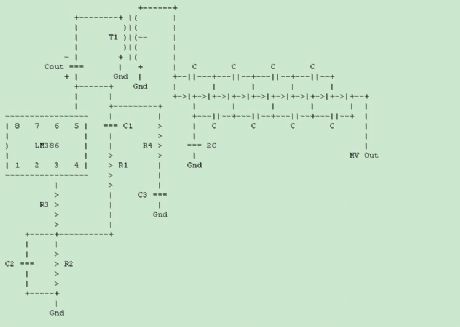
Connections to the LM386 Amplifier IC Not Shown:
Pins 2 and 4 Go to Gnd.Pin 6 gets B+ and also a capacitor (not shown) to Pin 4.This capacitor should be a .1 uF ceramic cap in parallel with an electrolytic cap of at least 10 uF. This circuit sometimes works better with these, but usually works without.
Components Shown Above:
The LM386 is an audio amplifier IC, Radio Shack Catalog # 276-1731.
T1 is a Radio Shack audio transformer, 273-1380. The red and white leads get the audio output from the LM386. (One grounded, one fed from Cout.) The blue and green leads feed the voltage multiplier. (One grounded, one feeds the first diode.)
Cout is at least 100 uF. The positive terminal goes to Pin 5 of the LM386, the negative terminal goes to the transformer.
The eight capacitors labeled C should be .1 to 1 uF rated at least 50 volts, preferably at least 100 volts. They will typically get 70 volts.The capacitor labeled 2C should be .2 to 2.2 uF rated at least 35 volts.For best results, C should be at least .2uf, preferably at least .47 uF. 2C should be at least .47 uF, preferably at least 1 uF.
The nine diodes are 1N914/1N4148. (R.S. Cat. # 276-1620 for 50 diodes or 276-276-1122 for ten diodes)
The two capacitors C1 and C2 should be .01 uF, preferably not a Z5U ceramic. R.S. Cat. # 272-1065 works well.
The resistors R1 and R2 are 4.7K.
R3 is a 10K resistor that I recommend, even though none at all usually works.
R4 is a 10 ohm resistor and C3 is a .1 uF capacitor. These are recommended in documentation for the LM386 in order to avoid ultrasonic oscillation. However, the LM386 usually does not oscillate if these are omitted.
Brief Description of this Circuit and How it Works
The LM386 audio amplifier, R1 and R2, and C1 and C2 are used to make a crude Wien bridge oscillator. The R1-R2-C1-C2 network has minimum loss and no phase shift at approx. 3.5 kilohertz and serves as the positive feedback route for the oscillator. If an automatic gain/level control circuit was added to keep the oscillation from building up to the point that the LM386 clips, this circuit would be a sinewave oscillator. Instead, the oscillation rapidly builds up to where severe clipping occurs.
The transformer steps the output AC of the 386 by a factor of about 10.
The nine diodes and nine capacitors form a voltage multiplying rectifier circuit. The DC output voltage is (not quite due to diode losses) nine times the peak voltage of the AC delivered by the transformer.
How to Use This Circuit and What to Expect
This circuit works from 4 to 12 volts DC. However, the power output is quite unimpressive with supply voltages under 8-9 volts or so. At 9 volts, this circuit charges up capacitors at an average wattage of .4 watt. A 200 uF capacitor would be charged to 250 volts in approximately 16 seconds.
At voltages near and above 9 volts, the rated limits of some of the components in this circuit are pushed. However, this circuit seems to work at up to 12 volts without anything burning out, or at least not too quickly. However, the LM386 seems to get rather hot at 12 volts. This circuit should be used as a cheap-and-dirty experimenter's circuit rather than a highly reliable circuit unless the supply voltage is near or under 7 volts. It is not a really ideal inverter circuit but a cheap-dirty one that can be made from Radio Shack parts.
The ultimate output voltage with a supply voltage of 9 volts is about 300 volts. If you want something different, you can use a different number of diodes and capacitors.
CAUTION - This circuit produces high voltage. Even if you get shocked by a part of the circuit that may not kill you, the shock might cause you bump into something else that might.
(View)
View full Circuit Diagram | Comments | Reading(652)
| Pages:79/2234 At 206162636465666768697071727374757677787980Under 20 |
Circuit Categories
power supply circuit
Amplifier Circuit
Basic Circuit
LED and Light Circuit
Sensor Circuit
Signal Processing
Electrical Equipment Circuit
Control Circuit
Remote Control Circuit
A/D-D/A Converter Circuit
Audio Circuit
Measuring and Test Circuit
Communication Circuit
Computer-Related Circuit
555 Circuit
Automotive Circuit
Repairing Circuit