
Circuit Diagram
Index 65
Door Alarm circuit
Published:2013/7/29 20:21:00 Author:muriel | Keyword: Door Alarm circuit
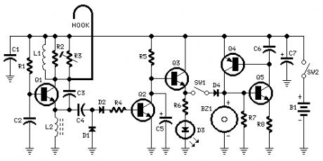
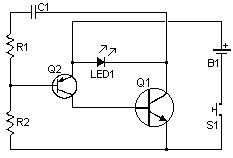
Parts:R1 1M 1/4W ResistorR2 3K3 1 or 2W Resistor (See Notes)R3 10K 1/2W Trimmer Cermet (See Notes)R4 33K 1/4W ResistorR5 150K 1/4W ResistorR6 2K2 1/4W ResistorR7 22K 1/4W ResistorR8 4K7 1/4W ResistorC1,C2 10nF 63V Ceramic or Polyester CapacitorsC3 10pF 63V Ceramic CapacitorC4,C6 100nF 63V Ceramic or Polyester CapacitorsC5 2µ2 25V Electrolytic CapacitorC7 100µF 25V Electrolytic CapacitorD1,D2,D4 1N4148 75V 150mA DiodesD3 5 or 3mm. Red LEDQ1,Q2,Q3,Q5 BC547 45V 100mA NPN TransistorsQ4 BC557 45V 100mA PNP TransistorL1 (See Notes)L2 10mH miniature InductorHook (See Notes)BZ1 Piezo sounder (incorporating 3KHz oscillator)SW1,SW2 SPST miniature Slider SwitchesB1 9V PP3 BatteryClip for PP3 Battery
Device purpose:This circuit emits a beep and/or illuminates a LED when someone touches the door-handle from outside. The alarm will sound until the circuit will be switched-off.The entire circuit is enclosed in a small plastic or wooden box and should be hanged-up to the door-handle by means of a thick wire hook protruding from the top of the case.A wide-range sensitivity control allows the use of the Door Alarm over a wide variety of door types, handles and locks. The device had proven reliable even when part of the lock comes in contact with the wall (bricks, stones, reinforced concrete), but doesn't work with all-metal doors.The LED is very helpful at setup.
Circuit operation:Q1 forms a free-running oscillator: its output bursts drive Q2 into saturation, so Q3 and the LED are off. When part of a human body comes in contact with a metal handle electrically connected to the wire hook, the body capacitance damps Q1 oscillations, Q2 biasing falls off and the transistor becomes non conducting. Therefore, current can flow into Q3 base and D3 illuminates. If SW1 is closed, a self-latching circuit formed by Q4 & Q5 is triggered and the beeper BZ1 is activated.When the human body part leaves the handle, the LED switches-off but the beeper continues to sound, due to the self-latching behavior of Q4 & Q5. To stop the beeper action, the entire circuit must be switched-off opening SW2.R3 is the sensitivity control, allowing to cope with a wide variety of door types, handles and locks.
Notes:L1 is formed winding 20 to 30 turns of 0.4mm. diameter enameled copper wire on R2 body and soldering the coil ends to the resistor leads. You should fill R2 body completely with coil winding: the final turn's number can vary slightly, depending on different 1 or 2W resistor types actual length (mean dimensions for these components are 13-18mm. length and 5-6mm. diameter).The hook is made from non-insulated wire 1 - 2mm. diameter (brass is well suited). Its length can vary from about 5 to 10cm. (not critical).If the device is moved frequently to different doors, Trimmer R3 can be substituted by a common linear potentiometer fitted with outer knob for easy setup.To setup the device hang-up the hook to the door-handle (with the door closed), open SW1 and switch-on the circuit. Adjust R3 until the LED illuminates, then turn slowly backwards the screwdriver (or the knob) until the LED is completely off. At this point, touching the door-handle with your hand the LED should illuminate, going off when the hand is withdrawn. Finally, close SW1 and the beeper will sound when the door-handle will be touched again, but won't stop until SW2 is opened.In regular use, it is advisable to hang-up and power-on the device with SW1 open: when all is well settled, SW1 can be closed. This precautionary measure is necessary to avoid unwanted triggering of the beeper. (View)
View full Circuit Diagram | Comments | Reading(1123)
Infrared gates
Published:2013/7/29 20:20:00 Author:muriel | Keyword: Infrared gates
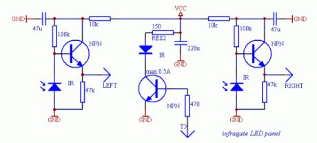

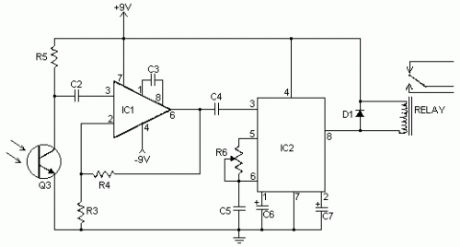
This is an infrared gate with two sensors planned to use in the wall in the way behind a door. It can be applied in a toilet to keep track of that someone is inside exceeding a certain amount of time. After that time elapsed, the circuit triggers the digital output wich can turn on a ventillator. The time period the output is turned on can be separately controlled by a second timer.If you plan to build this circuit, beware that you may have lots of difficulties though the schematic may seem simple. The construction of the circit requires some amount of equipment like an oscilloscope and a DVM, too. Without them, the device will do weird things you wouldn't expect, and even if it is correctly put together, you must adjust it with care both mechanically in its final place and electronically with the help of an oscilloscope. Only if you want to span about less than 20-30 inches with the infra diodes can forget about this calibration. Alternatively you can take ideas from this construction.
SchematicsThe device consists of several parts, the most critical one is the panel with the infra LEDs. I tried to use several receiver transistors, but best result was given by infra receiver diodes used in TV remote control receivers. The receiver diodes must be properly shielded from the transmitter LED(s) otherwise the infra light will surely drive the receiver with a large enough signal. These photodiodes should only see infrared light coming from the mirror. The two very sensitive receiver parts should also be isolated from the transmitter electrically or the TX signal will get across the wires to the RX lines, which results the same effect as weak optical shielding. Use metal shielding around the receiver amplifiers where possible. The infrared transmitter LEDs should be close in wavelength to the max. sensitivity band of the receivers. You can experiment with using more LEDs and more current testing several resistor values, but don't exceed the 500 mA current limit flowing on the diodes or they will burn out. Do not shield the transmitters, allow the maximum amount of infralight to reach the mirror to extend the possible range.
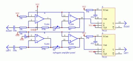
To start testing the infra LED panel, you wil need the infragate amplifier panel and the small transmiter driver. The TX driver will generate the digital signal for the LED driver on the LED panel. The digital signal is 1:10 on/off to achive good performance with lower power dissipation on the LEDs. Connect GND, VCC planes and LEFT, RIGHT wires of the LED panel with the amplifier panel, and drive the TX line from the TX driver. Now you are able to start testing and calibrating the analogue part of the circuit. If everything is ok, holding a mirror in front of the LED panel will reflect enough signal to overdrive the amplifier and you can check the output on the OPA 1, 7 pins with an oscilloscope. Taking the mirror farther on will result a weakening signal on the amplifier output. Set the orientation of the diodes to be able to get the maximum signal amplitude on the oscilloscope screen. This is the heaviest part of the work, don't deal too much with it until the complete circuit is not built. Just adjust a static state of the construction to give the maximum signal amplitude on the output when nothing is between the diodes and the mirror and give a small noise only when the line of sight is covered. If you are ready with it, you can adjust the schmitt triggers built of the other two OPA parts to generate TTL pulses when the analog signal is at its maximum and stay on the same DC level when the received signal is missing.
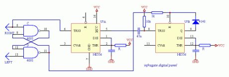
It is also important to protect the receiver diodes from direct light as natural light will weaken the sensitivity of the diodes, and lamps will transform the 50/60 Hz modulation present in the line power. Small noise is not problem, but the received signal from the TX generator should be stronger to be able to detect it. After the ST adjustments, connect LEDs to the 74123's TTL outputs through proper value resistors. The 74123 here is used as a demodulator. If there is a periodic signal change on the input, the output will be high, while if there is no activity on the input for a given period of time, the output falls low. When you cover the line of sight of one receiver diode, the corresponding LED turns off. There should not be any flickering in the turning on/off, the output should immediately respond to the change without blinking.
It is also important to protect the receiver diodes from direct light as natural light will weaken the sensitivity of the diodes, and lamps will transform the 50/60 Hz modulation present in the line power. Small noise is not problem, but the received signal from the TX generator should be stronger to be able to detect it. After the ST adjustments, connect LEDs to the 74123's TTL outputs through proper value resistors. The 74123 here is used as a demodulator. If there is a periodic signal change on the input, the output will be high, while if there is no activity on the input for a given period of time, the output falls low. When you cover the line of sight of one receiver diode, the corresponding LED turns off. There should not be any flickering in the turning on/off, the output should immediately respond to the change without blinking. (View)
View full Circuit Diagram | Comments | Reading(986)
Air Flow Detectors
Published:2013/7/29 20:18:00 Author:muriel | Keyword: Air Flow Detectors
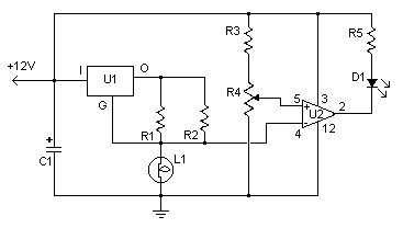
This simple circuit uses an incandescent lamp to detect airflow. With the filament exposed to air, a constant current source is used to slightly heat the filament. As it is heated, the resistance increases. As air flows over the filament it cools down, thus lowering it's resistance. A comparator is used to detect this difference and light an LED. With a few changes, the circuit can be connected to a meter or ADC to provide an estimation on the amount of air flow.
Parts:R1 100 Ohm 1/4W ResistorR2 470 Ohm 1/4W ResistorR3 10k 1/4W ResistorR4 100K 1/4W ResistorR5 1K 1/4W ResistorC1 47uF Electrolytic CapacitorU1 78L05 Voltage RegulatorU2 LM339 Op AmpL1 #47 Incandescent lamp with glass removed (See Notes )D1 LEDMISC Board, Wire, Sockets for ICs, etc.
Notes:1. The glass will have to be removed from L1 without breaking the filament. Wrap the glass in masking tape and it in a vise. Slowly crank down until the glass breaks, then remove the bulb and carefully peel back the tape. If the filament has broken, you will need another lamp. (View)
View full Circuit Diagram | Comments | Reading(3445)
73 MHz Hallogene Lamp Radio-Controlled
Published:2013/7/29 20:18:00 Author:muriel | Keyword: 73 MHz, Hallogene Lamp, Radio-Controlled

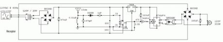
This circuit is a 73 MHz Hallogene Lamp Radio-Controlled. The purpose of it is to control the power state of a hallogene lamp by a remote control. When we press the push botton of the remonte control, the power state of the lamp will be changed, so, if the lamp was turned on, it will turned off and if it was turned on, it will turned off. If we press to the button another time, the same action will be occured. When the button is pressed, a LED indicator lights on the remote control.The system is consisted by two separate circuit. One is the remote control, or the emmetor. The other is the receptor, or the hallogene lamp controller. We plug the input of the lamp controller circuit to the 120VAC source of the sector to supply it. The lamp must be pluged to the output of the circuit to be supplied and controlled.The controller circuit has also an antenna to receive the signal of the remote control. The remote control has also an antenna to transmit the signal to the controller circuit and have to be powered by a 9V battery. Two things important for my circuit are not mentioned in the schematic. There are about the two logic component.The first one is the Schmitt trigger NOT gate (74LS14). Its Vcc pin must be connected to the output of the +5V regulator (7805). And its GND pin must be connected to the ground of the circuit. The second one is the JK Flip-Flop (74LS76). Its Vcc pin must be connected to the output of the +5V regulator (7805). And its GND pin must be connected to the ground of the circuit. (View)
View full Circuit Diagram | Comments | Reading(1000)
Unipolar Stepper Motor Controller
Published:2013/7/29 20:17:00 Author:muriel | Keyword: Unipolar Stepper , Motor Controller
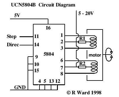
This is a very good integrated circuit. There is no need for any external glue logic to drive the circuit, there is only 2 pins to drive the motor, one for controlling the direction and the other to trigger the stepping pulses. It provides a very compact design that drives 5 or 6 or 8 wire stepper motors. The 5 or 8 wire stepper motors are treated as a variation on the 6 wire motor. That is, the 5 has the two common wires from the coils center taps joined inside the motor (saves joining them outside the motor), however some confusion may occur with the ends of the other coils as to which joins with which, however trial and error to determine this will not hurt anything. In the 8 wire motor case the joined center taps will have to worked out by you. You will know which coil is joined to which coil, however experimentation may be required to determine polarity.
The resistors R1 & R2 are only necessary if the supply voltage to the motors is above 10 volts or so, and are really only necessary near max voltages and tuning the response times of the motor for high speeds. See data sheets for details.There should be very little problem getting hold of six wire motors that make the connections obvious. These motors are by far the most common where any degree of power is required, e.g. in printers. Non-working dot matrix printers are fairly common now-a-days and the motors in them are excellent starting points for experimentation. You will also get belts, pulleys and gears thrown in (may be even a power supply if your are adventurous).
A very simple Printed Circuit Board Design
Features of the chip:1.5A Maximum Output Current35 V Output Sustaining voltageWave-Drive, Two-Phase, and Half Step FormatsInternal Clamp DiodesOutput enable controlPower on resetInternal Thermal ShutdownSequence ConnectionsTwo-Phase Drive Sequence Pin 9 GND Pin 10 GND (Simplest choice)Wave Drive Sequence Pin 9 5v Pin 10 GNDHalf Step Drive Sequence Pin 9 GND Pin 10 5VThis driver will allow you to scale up your project considerably as the power will be much greater with the bigger motors and higher voltages and currents. The draw back is that the engineering that goes along with them will also have to be more substantial. The larger stepper motors are very heavy for desktop models but will be very versatile for the larger experiment.
Commercial Kit and Data SheetsAn excellent, high quality kit (Nos:109) to experiment with this driver can be purchased fromWiltronics Research PTY LTD5-7 Ripon St (North)Ballarat 3350AUSTRALIAPhone (03)5331 1947It provides a 5 volt regulated supply, indicator LEDs, 555 oscillator for pulses and miniature switches to control direction and stepping modes. Single step or free funning can be chosen as well full data sheets provided. They also provide data sheets with the circuit. Contact them for prices. While not the cheapest way to go it is the best seen so far. (View)
View full Circuit Diagram | Comments | Reading(1971)
Fancontrol
Published:2013/7/29 20:16:00 Author:muriel | Keyword: Fancontrol
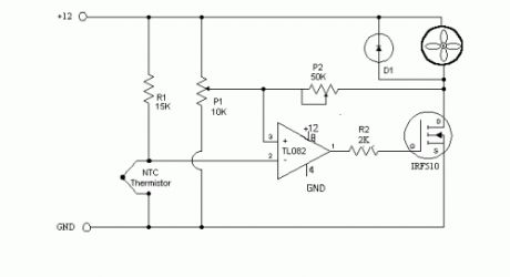
This is a simple circuit that will do what you want I believe.
R1 15k ohm resistorNTC Thermistor- 10k ohm, sold at Radio Shack in the states.P1 10k ohm potentiometer - sets the low speed(voltage) of the fans at the cool temperature. P2 50K ohm potentiometer - sets the gain of the circuit - how fast the voltage will rise to full output when the temp is higher. TL082 a op-amp that I had handy, most any single voltage op-amp should work. The TL082 is a dual op-amp if you want more then one controller on a board. note that the power and ground connections for the op-amp are not shown on the schematic. R2 - The TL082 is a fast op-amp, needed R2 to reduce oscillation. IRF-510 A 4 amp mos-fet in a TO-220 case. Bascially as the voltage on the gate rises the mos-fet will conduct more current. note 1 there are also IRF-520 and 530 versions that will handle more current. note 2 Even at 5 watts the mos-fet will disapate some heat and will need to be heat-sinked or at least in the air flow path. the large metal part of the fet will be at drain(D) voltage level. Do not attach to case. D1, almost any diode, 1N4001 should work,it conducts back around the fan when the mos-fet turns off. As the fan continues spinning it will produce a voltage on the drain lead of the fet. D1 will limit that voltage. Adjustment, easiest if you have a voltmeter but can be done without. Get the thermistor at room temp. Adjust P1 for the low speed that you want your fans to run at. Heat the thermistor to the high temp you want the fans at full speed. ( I stuck it under my tongue) Adjust P2 until the fans are at full speed( with voltmeter the highest voltage you can get) then adjust P2 until the speed/voltage just begins to drop off. Most fan specs that I have seen show a low voltage limit of around 7 volts. Some of the smaller 80mm fans have a lower limit of 8 volts. If you set the low voltage to low the fans may stall until the thermistor heats up enough. Let me know if you build this circuit and how it works for you. corrected, single voltage op-amps should be used, OP-07 is a dual voltage. (View)
View full Circuit Diagram | Comments | Reading(1331)
Salt Taster
Published:2013/7/29 20:12:00 Author:muriel | Keyword: Salt Taster
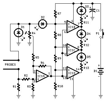
Parts:R1 470R 1/4W ResistorR2,R5 10K 1/4W ResistorsR3,R6 220K 1/4W ResistorsR4 5K 1/2W Trimmer CermetR7 680R 1/4W ResistorR8 2K2 1/4W ResistorR9,R10,R11,R12,R13 1K 1/4W ResistorsC1 100µF 25V Electrolytic CapacitorD1,D2,D3 3 or 5mm. Red LEDsD4 3 or 5mm. Green LEDD5 3 or 5mm. Yellow LEDIC1 LM324 Low Power Quad Op-ampP1 SPST PushbuttonProbes (See Text)B1 9V PP3 BatteryClip for PP3 Battery
Device purpose:This circuit was designed to detect the approximate percentage of salt contained in a liquid. After careful setting it can be useful to persons needing a quick, rough indication of the salt content in liquid foods for diet purposes etc.
Circuit operation:IC1A op-amp is wired as a DC differential amplifier and its output voltage increases as the DC resistance measured at the probes decreases. In fact, fresh water has a relatively high DC resistance value that will decrease proportionally as an increasing amount of salt is added.IC1B, IC1C and IC1D are wired as comparators and drive D5, D4 and D3 in turn, as the voltage at their inverting inputs increase. Therefore, no LED will be on when the salt content of the liquid under test is very low, yellow LED D5 will illuminate when the salt content is low, green LED D4 will illuminate if the salt content is normal and red LED D3 will illuminate if the salt content is high.D1 and D2 are always on, as their purpose is to provide two reference voltages, thus improving circuit precision. At D2 anode a stable 3.2V supply feeds the non-inverting inputs of the comparators by means of the reference resistor chain R8, R9 and R10. The 1.6V reference voltage available at D1 anode feeds the probes and the set-up trimmer R4.One of these two red LEDs may be used as a pilot light to show when the device is on.
Probes:It was found by experiment that a good and cheap probe can be made using a 6.3mm. mono jack plug. The two plug leads are connected to the circuit input by means of a two-wire cable (a piece of screened cable works fine).The metal body of the jack is formed by two parts of different length, separated by a black plastic ring. You should try to cover the longest part with insulating tape in order to obtain an exposed metal surface of the same length of the tip part, i.e. about 8 to 10mm. starting from the black plastic ring.In the prototype, three tablespoons of liquid were poured into a cylindrical plastic cap of 55mm. height and 27mm. diameter, then the metal part of the jack probe was immersed in the liquid.
Notes:Wait at least 30 seconds to obtain a reliable reading.Wash and wipe carefully the probe after each test.To setup the circuit and to obtain a more precise reading, you may use a DC voltmeter in the 10V range connected across pin #1 of IC1A and negative supply.Set R4 to obtain a zero reading on the voltmeter when the probe is immersed in fresh water.You may change at will the threshold voltage levels at which the LEDs illuminate by trimming R4. Vary R8 value to change D4 range and R9 value to change D5 range.P1 pushbutton may be substituted by a common SPST switch. (View)
View full Circuit Diagram | Comments | Reading(0)
DC Motor Control Circuits
Published:2013/7/29 20:12:00 Author:muriel | Keyword: DC Motor Control Circuits

Notes:Here, S1 and S2 are normally open , push to close, press button switches. The diodes can be red or green and are there only to indicate direction. You may need to alter the TIP31 transistors depending on the motor being used. Remember, running under load draws more current. This circuit was built to operate a small motor used for opening and closing a pair of curtains. As an advantage over automatic closing and opening systems, you have control of how much, or how little light to let into a room. The four diodes surriunding the motor, are back EMF diodes. They are chosen to suit the motor. For a 12V motor drawing 1amp under load, I use 1N4001 diodes. (View)
View full Circuit Diagram | Comments | Reading(1085)
Plants Watering Watcher
Published:2013/7/29 20:10:00 Author:muriel | Keyword: Plants Watering Watcher
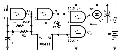
Parts:R1 470K 1/4W ResistorR2 3K3 1/4W ResistorR3 100K 1/2W Trimmer CermetC1 1nF 63V Polyester CapacitorC2 47µF 25V Electrolytic CapacitorD1 1N4148 75V 150mA DiodeD2 5mm. Red LEDIC1 4093 Quad 2 input Schmitt NAND Gate ICP1,P2 Probes (See text)SW1 SPST Slider SwitchB1 3V Battery (2 AA 1.5V Cells in series)
Device purpose:This circuit is intended to signal when a plant is needing water. A LED illuminates at maximum brightness when the ground in the flower-pot is too dry: it dims gradually as the water's content in the pot grows, turning off when the optimum moisture's level is reached. This condition is obtained trimming R3.
Circuit operation:IC1D forms a square wave oscillator with approx. 10/90 mark-space ratio. It feeds the output probe P1 and its signal, inverted by IC1A is compared with that picked-up by P2 in the NAND gates IC1B & IC1C in parallel, driving the LED. When a low resistance exists between the probes, due to an high water's content in the flower-pot, the LED is off, turning gradually on as the resistance between the probes increases.
Notes:A square wave is used to avoid probes' oxidization.Probes can be long nails, carbon rods obtained from disassembled exhausted 1.5V batteries, or even a couple of screwdrivers.The probes must be driven in the pot's ground a few inches apart.Due to 3V supply, the LED needs not a limiting resistor.Power consumption: LED off = 50µA; LED full on = 1mA.To switch-off the circuit, you can short the probes. In this case SW1 can be omitted.Using an high-efficiency LED, brightness variations are better emphasized. In this case a limiting resistor could be necessary. (View)
View full Circuit Diagram | Comments | Reading(1109)
Simple DC motor PWN speed control
Published:2013/7/29 20:09:00 Author:muriel | Keyword: Simple DC motor, PWN speed control
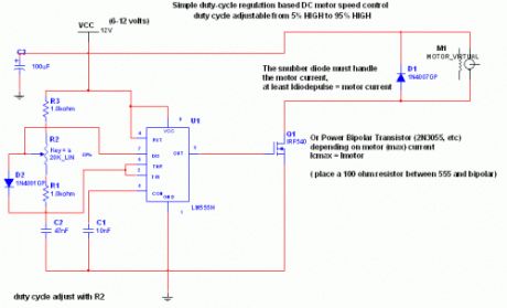
Circuit Explaination:The 555 Ic is wired as an astable and the frequency is constant and independent of the duty cycle, as the total resistance (R charge + R discharge, notice the diode) is constant and equal to 22Kohm (givin a frequency of about 1Khz, notice the hum).When the potentiomenter is all up, the Rcharge resistance is 1,0 Kohm (the diode prevents the capacitor to charge through the second potentiometer section and the other 1,0 Kohm resistor) , and Rdischarge is 21 Kohm, giving a 5% on duty cycle and a 1Khz frequency.When the potentiomenter is all down, the Rcharge resistance is 21,0 Kohm (the diode prevents the capacitor to charge through the second potentiometer section and the other 1,0 Kohm resistor) , and Rdischarge is 1 Kohm, giving a 95% on duty cycle and a 1Khz frequency.When the potentiomenter is at 50% , the Rcharge resistance is 11,0 Kohm (the diode prevents the capacitor to charge through the second potentiometer section and the other 1,0 Kohm resistor) , and Rdischarge is 11 Kohm, giving a 50% on duty cycle and a 1Khz frequency.The 555 provide good current capability to drive the mosfet fast and to drive a bipolar transistor.I actually use this system to drive the DC motor of my small Rotary spark gap Tesla coil at variable speedIf you are disgusted by the 1Khz hum of the motor try to rise the frequency out of the audible range (replacing the potenziometer), but rembember that at higher frequency inductive reactance of motor rises so the the efficiency would drop.
Important:Obviously the mosfet (or bipolar) must have enough current capability to drive the motor, so the drain (or collector) current must be equal to maximum motor current (at power supply voltage, when it is blocked). The snubber diode too, because it shorts the motor on the off cycle. Both mosfet (or bipolar) and diode have to be hooked (if you don't want them cooked ;-) ) to a heatsinkif the max motor current is more than 100 or 200mA. I suggest to not stress to much the motor with too much work because it overheats both motor, transistor and diode.If you don't want braking in the off cycle just place a resistor in series with the snubber diode, it should rise a bit efficiency but have more inertia when slowing the motor down. The value of the resistor must be R=V(breakdown transistor) / Imax, and the power should be 5W. Mosfets have internal zener diode, but don't count on it ;-) (View)
View full Circuit Diagram | Comments | Reading(1478)
Fridge door Alarm circuit
Published:2013/7/29 20:09:00 Author:muriel | Keyword: Fridge door , Alarm circuit
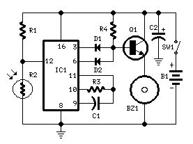
Parts:R1 10K 1/4W ResistorR2 Photo resistor (any type)R3,R4 100K 1/4W ResistorsC1 10nF 63V Polyester CapacitorC2 100µF 25V Electrolytic CapacitorD1,D2 1N4148 75V 150mA DiodesIC1 4060 14 stage ripple counter and oscillator ICQ1 BC337 45V 800mA NPN TransistorBZ1 Piezo sounder (incorporating 3KHz oscillator)SW1 Miniature SPST slide SwitchB1 3V Battery (2 AA 1.5V Cells in series)
Circuit operation:This circuit, enclosed in a small box, is placed in the fridge near the lamp (if any) or the opening. With the door closed the interior of the fridge is in the dark, the photo resistor R2 has a high resistance (>200K) thus clamping IC1 by holding pin 12 high. When a beam of light enters from the opening, or the fridge lamp lights, the photo resistor lowers its resistance (<2K), pin 12 goes low, IC1 starts counting and, after a preset delay (20 seconds in this case) the piezo sounder beeps for 20 sec. then stops for the same lapse of time and the cycle repeats until the fridge door closes. D2 connected to pin 6 of IC1 makes the piezo sounder beeping 3 times per second.
Notes:Connecting D1 to pin 2 of IC1 halves the delay time.Delay time can be varied changing C1 and/or R3 values.Any photo resistor type should work well.Current drawing is insignificant, so SW1 can be eliminated.Place the circuit near the lamp and take it away when defrosting, to avoid circuit damage due to excessive moisture.Don't place it in the freezer. (View)
View full Circuit Diagram | Comments | Reading(959)
Circuit diagram For Receiver
Published:2013/7/29 20:08:00 Author:muriel | Keyword: Receiver
View full Circuit Diagram | Comments | Reading(730)
Circuit diagram For Transmitter
Published:2013/7/29 20:08:00 Author:muriel | Keyword: Transmitter
View full Circuit Diagram | Comments | Reading(701)
Auto Heat Limiter for Soldering Iron
Published:2013/7/29 20:07:00 Author:muriel | Keyword: Auto Heat Limiter, Soldering Iron
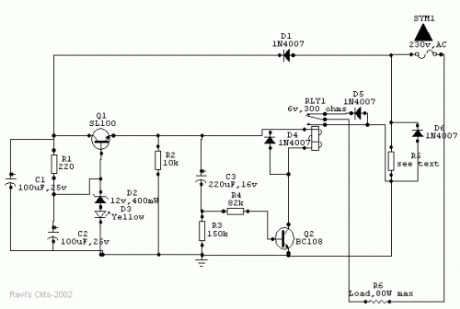
Wattage of load 10W 18W 25W 35W 65W 80WValue of R5 (in ohms) 330 180 136 (68+68) 100 56 44 (22+22)Wattage of R5 (in watts) 01 02 02 04 05 6.5
Usually a soldering iron takes a couple of minutes to get adequately heated up to melt the solder, after which the heat generated is much above the requirement and is wasted. Moreover, excessive heat decreases the life of the bit and the element, causing serious damage to the components.The above circuit solves this problem in a simple and inexpensive way and could be used to various types of loads up to 80watts.
How it worksOnce the main is switched on, an approximate 15v drop of the positive half cycle across R5 is detected and supplied to Q1 (SL100 or D313), which acts as a voltage regulator. Zener diode D2 together with diode D3 (yellow LED) stabilizes the emitter voltage of Q1 at 13.2Vdc, which is then delivered to the relay circuit built around Q2 and C3. Capacitor C3 charges through the base-emitter path of Q2 and causes the relay to actuate, which in turn allows both the half cycles of the AC mains to flow through diode D6 and R5 to the load to heat it up at a normal rate.After a certain lapse of time (about 2 minutes preset) C3 saturates and Q2 stops conducting through the relay, thus switching on series diode D5 to allow only half of the Ac cycle through the load.After switching off the system, C3 discharges very slowly through R2 and R3. Before C3 gets completely discharged, if the power is switched on again, C3 takes a shorter time to reach the saturation level, thus switching series diode D5 much earlier than the preset time to prevent double heating of the load.However, if the circuit is switched on only after a few seconds of switching off, C3 gets no time to discharge and the relay does not actuate at all. Moreover, if the relay circuit fails due to any reason and Q2 does not conduct, no harm is done to the load because in that case D5 remains in series with it. Thus the circuit offers complete protection to the load.As stated earlier, the given value of C3 gives a delay of 2 minutes. However, a 1000mfd capacitor can also be used to produce a 4.5-minute delay. R5 maintains a drop of about 15V across itself. So for use in different load conditions its value changes as shown in Table 1.The whole circuit can be mounted on a PCB and fitted in an adapter case (7.6cm X 5.1cm X 6.4cm) and used as a mains plug. Since R5 gets heated up during the operation, it should be kept well isolated from the other components.
PartsR1 - 220 ohmsR2 – 10KR3 – 150KR4 – 82K(all resistors should be 5% close tolerance)C1- 100 uf, 25V dc working electrolyticC2 – 100 uf, 25V dc working electrolyticC3 – 220 uf, 16V dc working electrolytic(advisable to use close tolerance Caps. to obtain correct timings)D1, D4, D5, & D6 – IN4007D2 – 12V 400mw, Zener diodeD3 – Yellow LEDRLY1 – 6V, 300 ohms DC relayQ1 – SL100 or D313Q2 – BC108 (View)
View full Circuit Diagram | Comments | Reading(1925)
Voice activated switch
Published:2013/7/29 20:06:00 Author:muriel | Keyword: Voice activated switch

This circuit uses an MC2830 to form a voice activated switch ( VOX ). A traditional VOX circuit is unable to distinguish between voice and noise in the incoming signal. In a noisy environment, the switch is often triggered by noise, or the activation sensitivity must be turned down. This circuit overcomes this weakness. The switch is activated by voice level above the noise and not activated by background noise. This is done by utilizing the differences in voice and noise waveforms. Voice waveforms generally have a wide range of variation in amplitude, whereas noise waveforms are more stable. The sensitivity of the voice activation depends on the value of R6. The voice activation sensitivity is reduced from 3.0dB to 8.0dB above the noise if R6 changes from 14k to 7.0k . (View)
View full Circuit Diagram | Comments | Reading(2558)
Infrared Detector
Published:2013/7/29 20:05:00 Author:muriel | Keyword: Infrared Detector
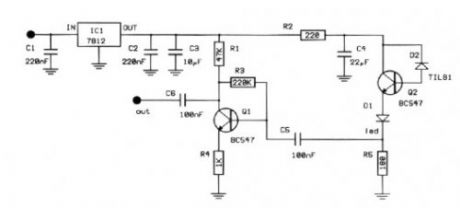
The infra red radiation is a region with bigger length of wave from the visible spectrum. It is a region which our eye does not conceive, the consequences however which we felt as heat of. The manufacture that to you we propose receives this region and on one side us notice with optical clue, otherwise we can observe the configuration of width of radiation.
The circuit of manufacture appears in form. sensory is a passage of silicon with relatively big surface. This passage when it is not litted up by infra red light has very big resistance of order of Mohm. this resistance is reversely proportional at approach of brightness. The type of passage is not critical, in the place can enter anyone. The resistance of passage him we use in order to polarize a transistor of npn type BC547. The photodiode enters between in the collector and in the base. The current that leak the passage is multiplied by the b of transistor and it is presented in the emitter of transistor. This current is enough in order to it leads and it turns on a Led . En line with this circuit exists a resistance in order to it limits his current.
The infra red radiation has very a lot of applications in the industry and in the trade. The more important perhaps application they are telecontrols, that exist everywhere. The proposed manufacture is based on a passage of silicon which is connected in amplifier. The exit of amplifier leads a Led. Each time where lights it means that hits infrared radiation in the sensor. The circuit allocates moreover a exit in that we can connect a small acoustic amplifier or even a oscilloscope.
In utmost this resistance is presented a tendency of proportional incident radiation. If in deed the radiation has been shaped at width then will be presented in utmost her component of configuration. If for example falls in the photodiode for some reason a fraction of beam from infrared laser with configuration by sound then in utmost the resistance will be presented wave the sound. In this point we added a exit for oscilloscope for a small amplifier. The tendency of catering should have noise and be clean. Stabilised power supply it ensures this operation. The stabilisation becomes with stabilizer of tendency 7808.
In order to you make the manufacture you will need printed that exists in what form , in you will place the materials according to form. At the placement it should you give few attention in the right time of semiconductors, transistors passages and stabilizer of tendency. In the circuit of emitter Q2 it exists a led, which it will turn on each time where incident infrared radiation in the photodiode. In the exit of Q1 you will find the same signal strengthened. This signal will contain the at width unmodulate information that will have the radiation (or this emanates from telecontrols, or from laser).
PartsR1 47K R2 220 R3 220K R4 1K R5 180 C1,2 220nFC3 10uFC4 22uF C5 100nFC6 100nFIC1 7812Q1 BC547Q2 BC547D1 LedD2 TIL81 (View)
View full Circuit Diagram | Comments | Reading(2383)
UNEVEN CLICKS
Published:2013/7/29 1:54:00 Author:lynne | Keyword: UNEVEN CLICKS
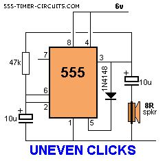
This circuit produces two clicks then a short space before two more clicks etc. Changing the voltage on pin, 5 via the diode, adjusts the timing of the chip.
(View)
View full Circuit Diagram | Comments | Reading(827)
Up/Down Fading LED
Published:2013/7/29 1:51:00 Author:lynne | Keyword: Up/Down Fading LED
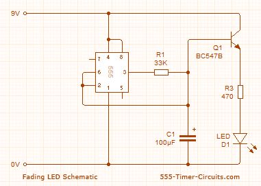
These two circuits make a LED fade on and off. The first circuit charges a 100u and the transistor amplifies the current entering the 100u and delivers 100 times this value to the LED via the collector-emitter pins. The circuit needs 9v for operation since pin 2 of the 555 detects 2/3 Vcc before changing the state of the output so we only have a maximum of 5.5v via a 470R resistor to illuminate the LED. (View)
View full Circuit Diagram | Comments | Reading(2083)
WAILING SIREN
Published:2013/7/29 1:49:00 Author:lynne | Keyword: WAILING SIREN

By pressing the button, the wailing sound increases. Releasing the button decreases the wailing. The circuit automatically turns off after about 30 seconds.
(View)
View full Circuit Diagram | Comments | Reading(0)
Servo Controller
Published:2013/7/29 1:42:00 Author:lynne | Keyword: Servo Controller

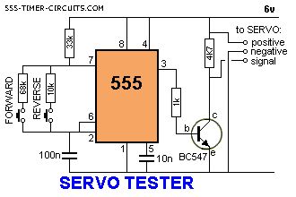

This circuit can be used to manually turn a servo clockwise and anti-clockwise. By pushing the forward or reverse button for a short period of time you can control the rotation of the servo. It will also test a servo. Here is a photo of a kit from Cana Kit for $10.00 plus postage (it is a slightly different circuit) and a motor and gearbox, commonly called a servo. The output shaft has a disk or wheel containing holes. A linkage or push-rod is fitted to a hole and when the disk rotates, the shaft is pushed and pulled. The shaft only rotates about 180� to actuate flaps or ailerons etc.
A pot can be used to control the position of the servo by using the following circuit. It produces a positive pulse between about 0.9 milliseconds and 2.1 milliseconds. The off period between pulses is about 40 milliseconds. This can be shortened by reducing the value of the 3M3 resistor. (View)
View full Circuit Diagram | Comments | Reading(1821)
| Pages:65/2234 At 206162636465666768697071727374757677787980Under 20 |
Circuit Categories
power supply circuit
Amplifier Circuit
Basic Circuit
LED and Light Circuit
Sensor Circuit
Signal Processing
Electrical Equipment Circuit
Control Circuit
Remote Control Circuit
A/D-D/A Converter Circuit
Audio Circuit
Measuring and Test Circuit
Communication Circuit
Computer-Related Circuit
555 Circuit
Automotive Circuit
Repairing Circuit