
Circuit Diagram
Index 64
Tan Timers
Published:2013/7/30 20:43:00 Author:muriel | Keyword: Tan Timers
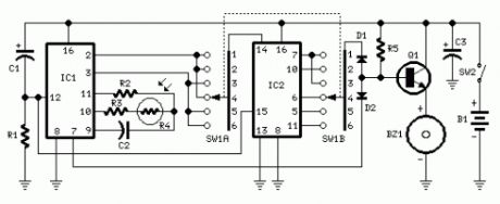
Parts:R1 47K 1/4W ResistorR2 1M 1/4W ResistorR3,R5 120K 1/4W ResistorsR4 Photo resistor (any type)C1,C3 10µF 25V Electrolytic CapacitorsC2 220nF 63V Polyester CapacitorD1,D2 1N4148 75V 150mA DiodesIC1 4060 14 stage ripple counter and oscillator ICIC2 4017 Decade counter with 10 decoded outputs ICQ1 BC337 45V 800mA NPN TransistorSW1 2 poles 6 ways Rotary Switch (see notes)SW2 SPST Slider SwitchBZ1 Piezo sounder (incorporating 3KHz oscillator)B1 3V Battery (two 1.5V AA or AAA cells in series etc.)
Device purpose:This timer was deliberately designed for people wanting to get tanned but at the same time wishing to avoid an excessive exposure to sunlight.A Rotary Switch sets the timer according to six classified Photo-types (see table).A Photo resistor extends the preset time value according to sunlight brightness (see table).When preset time ends, the beeper emits an intermittent signal and, to stop it, a complete switch-off of the circuit via SW2 is necessary.Photo-type, Features and Exposure timeI & children Light-eyed, red-haired, light complexion, freckly 20 to 33 minutesII Light-eyed, fair-haired, light complexion 28 to 47 minutesIII Light or brown-eyed, fair or brown-haired, light or slightly dark complexion 40 to 67 minutesIV Dark-eyed, brown-haired, dark complexion 52 to 87 minutesV Dark-eyed, dark-haired, olive complexion 88 to 147 minutesVI The darkest of all 136 to 227 minutes[color=green]Note that pregnant women belong to Photo-type I[/color]
Notes:Needing only one time set suitable for your own skin type, the rotary switch can be replaced by hard-wired links.A DIP-Switch can be used in place of the rotary type. Pay attention to use only a switch at a time when the device is off, or the ICs could be damaged. (View)
View full Circuit Diagram | Comments | Reading(804)
Periodic Timers
Published:2013/7/30 20:43:00 Author:muriel | Keyword: Periodic Timers

A switched timer with equal make and equal space periods timing adjustable from over 6 minutes to 38 minutes.
Notes:This timer circuit is similar to the 5 to 30 minute timer except that when switch S1 is closed, the on/off action of the circuit will continue indefinately until S1 is opened again. A 7555 time and low leakage type capacitor for C1 must be used. The 6 way rotary switch S3 adds extra resistance in series to the timing chain with each rotation, minimum resistance point a maximum point f . The 7555 is wired as an equal mark/space ratio oscillator, the timing resistor chain R1 to R6, being connected back to the output of the timer at pin 3.The output pulse duration is defined as:-
T = 1.4 R1 C1
This gives on and off times of about 379 seconds for postion a of S3 (just over 6 minutes), to about 38 minutes at point f . The times may of coourse be varied by altering R1 to R6 or C1. (View)
View full Circuit Diagram | Comments | Reading(997)
Reverse Bias Oscillators
Published:2013/7/30 20:41:00 Author:muriel | Keyword: Reverse Bias Oscillators

There are a number of npn transistors that will oscillate in the audio range when reverse biased. Minimum supply voltage is 7V for low power transistors such as BC109, BC238 and 2N2222A, it becomes 12V for medium power transistors such as BD139 and is 16V for power transistors as BUX22 and 2N6543. Current drain is 4mA at 9V and frequency of oscillation is 550Hz. The base is normally left open. (View)
View full Circuit Diagram | Comments | Reading(851)
Precision Metronome and Pitch generator
Published:2013/7/30 20:41:00 Author:muriel | Keyword: Precision Metronome, Pitch generator

Parts:R1 1M 1/4W ResistorR2 22K 1/4W ResistorR3 6K8 1/4W ResistorR4 4K7 1/4W ResistorR5 47K 1/4W ResistorR6 100K 1/4W ResistorR7 39K 1/4W ResistorR8 12K 1/4W ResistorC1 47pF 63V Ceramic CapacitorC2 2-22pF 63V Ceramic TrimmerC3 470pF 63V Ceramic CapacitorC4 10pF 63V Ceramic CapacitorC5 100nF 63V Polyester CapacitorC6 220nF 63V Polyester CapacitorC7 22µF 25V Electrolytic CapacitorD1-D15 1N4148 75V 150mA DiodesIC1 4060 14 stage ripple counter and oscillator ICIC2 4082 Dual 4 input AND gate ICIC3 4520 Dual binary up-counter ICIC4 4518 Dual BCD up-counter ICIC5 4046 Micropower Phase-locked Loop ICIC6 4040 12 stage ripple counter ICQ1 BC337 45V 800mA NPN TransistorXTAL 2.4576 MHz Miniature Quartz crystalSW1 BCD Miniature Thumbswheel Switch (units)SW2 BCD Miniature Thumbswheel Switch (tens)SW3 BCD Miniature Thumbswheel Switch (hundreds)SW4 SPST Slider Switch (On-off)SW5 SPDT Slider Switch (Metronome-Pitch)SPKR 8 Ohm, 50 mm. LoudspeakerB1 9V PP3 BatteryClip for 9V PP3 Battery
Circuit operation:CMos IC1 and IC2B quad AND gate form a 2.4576 MHz crystal oscillator plus a 2400 times divider. IC3A provides further division by 16, obtaining a 64 Hz stable frequency square wave. This frequency is multiplied by operation of Phase Locked Loop IC5, double decade divider IC4 and IC3B 4 bit binary divider, by the number set by three miniature BCD thumbswheel switches SW1, SW2 and SW3: units, tens and hundreds respectively.Connecting, by means of SW5, Q1 base to pin 2 of IC6, we obtain after a 64 times division, the same frequency set by thumbswheel switches with quartz precision, and no need for a scale indicator.Volume regulation of the pitch generator is obtained trimming resistor R5. In the same manner, with SW5 set to metronome, the small speaker reproduces the frequency set by thumbswheel switches but divided by 3840, thus obtaining beats per minute ratio (View)
View full Circuit Diagram | Comments | Reading(1150)
Sound Effects Generator 3
Published:2013/7/30 20:40:00 Author:muriel | Keyword: Sound Effects Generator 3

Notes:All sound effects are generated internally by the HT2884 IC. Power is a 3 Volt battery, but the IC will work with any voltage between 2.5 and 5 Volts. Switch S1 is the on / off switch. The output at pin 10 is amplified and drives a small 8 ohm loudspeaker. Pressing S3 once will generate all the sounds, one after another. S2 can be used to produce a single sound effect, next depression gives the next sound effect. There are 2 lazer guns, 1 dual tone horn sound, 2 bomb sounds, 2 machine gun sounds and a rifle shot sound. Standby current is about 1 uA at 3 Volt, so battery life is very economical. The IC may be obtained from Maplin Electronics order code AZ52G. (View)
View full Circuit Diagram | Comments | Reading(856)
Low-distortion Audio-range Oscillators
Published:2013/7/30 20:39:00 Author:muriel | Keyword: Low-distortion, Audio-range Oscillators
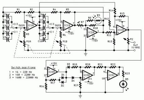
Parts:P1 10K Log. Potentiometer (Dual-ganged)P2 2K2 Linear PotentiometerR1,R2,R4,R5 3K3 1/4W ResistorsR3,R6 820R 1/4W ResistorsR7 10K 1/2W Trimmer CermetR8 22K 1/4W ResistorR9 Photo resistor (any type)R10 8K2 1/4W ResistorR11,R12,R14,R15 3K3 1/4W ResistorsR13 2K7 1/4W ResistorR16--R20 3K3 1/4W ResistorsR21 56K 1/4W ResistorR22 68K 1/4W ResistorR23 1K 1/4W ResistorC1,C6 220pF 63V Polystyrene CapacitorsC2,C7 8n2 63V Polyester CapacitorsC3,C8 82nF 63V Polyester CapacitorsC4,C9 150nF 63V Polyester CapacitorsC5,C10 680nF 63V Polyester CapacitorsD1--D4 1N4148 75V 150mA DiodesD5 LED 5mm. RedIC1,IC2 NE5532 Low noise Dual Op-ampsIC3 TL084 Quad BIFET Op-AmpSW1 2 poles 3 ways rotary switch
Comments:Producing low-distortion sine waves, this oscillator operates over the range 16 to 22000 Hz. The circuit is based on two articles that have appeared earlier in Wireless World - Roger Rosens' Phase -Shifting Oscillator , February 1982 pp. 38-41, and J. L. Linsley Hood's Wien-Bridge Oscillator with low harmonic distortion from May 1981 pp. 51-53.This design features the simplicity of the Rosens' circuit but avoids the use of a thermistor. Instead, oscillator stability is controlled by means of a common photo-resistor driven by a LED, as suggested in the Linsley Hood article.There is no settling time when the oscillator's frequency is changed and no bouncing of the output waveform. Use of an expensive and sometimes difficult to obtain thermistor is avoided.
Technical data:Output voltage:Sine wave, 1V RMS max. Total harmonic distortion @ 1V RMS output:Frequency Reading100Hz = 0.0035%300Hz = 0.0028%1kHz = 0.002 %3kHz = 0.002 %10kHz = 0.001 %
Notes:Any common photo-resistor and 5mm. red LED can be used, provided they are in close contact and enclosed in a light-proof small box. I used the metal screen of a small IF transformer for AM transistor radios sealed with black insulating tape.The 10K trimmer must be set to obtain a 1V RMS output.The circuit must be supplied by a + and - 15V dual regulated supply. Common 7815 and 7915 regulator ICs should be used for this purpose.
This circuit was awarded with publication in ELECTRONICS WORLD Circuit Ideas , February 2003 issue, page 38.
(View)
View full Circuit Diagram | Comments | Reading(1085)
Dome Lamp Dimmer
Published:2013/7/30 20:38:00 Author:muriel | Keyword: Dome Lamp Dimmer
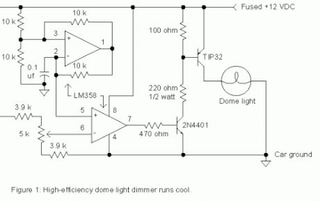
There are times when a little light inside the car would greatly assist one of the passengers but the dome light is too bright for safe driving. The dimmer circuit in fig. 1 may be added to an existing dome light or included with a new passenger spot lamp. The upper op-amp generates a 700 Hz sawtooth waveform which is compared to a setpoint voltage by the lower op-amp. When the sawtooth voltage is above the setpoint, the transistors turn on supplying current to the bulb. The setting of the potentiometer determines the width of the pulses sent to the lamp and therefore the average voltage. The lamp is dim when the potentiometer is set near the higher voltage. Since the TIP32 switches on and off instead of simply dropping the voltage like a power rheostat, the power it dissipates remains low and a heat sink is not necessary.
Many autos run power to lamps with only one wire using the car body for the return current path so the dimmer must interrupt the positive lead as shown. Simply cut the wire leading to the lamp and connect the lamp end to the collector of the TIP32 and connect the battery end to the circuit power input. Run an additional ground wire to the auto chassis from the circuit. This ground wire will not carry much current and may be a smaller gauge. (View)
View full Circuit Diagram | Comments | Reading(961)
NE555 Basic Monostable
Published:2013/7/30 20:37:00 Author:muriel | Keyword: NE555, Basic Monostable
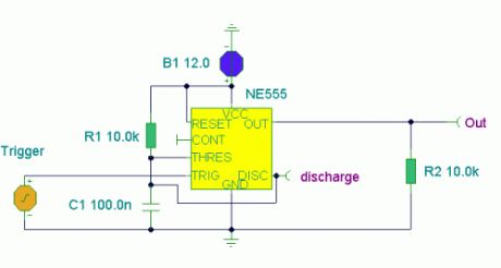
Notes:Here the popular 555 timing IC, is wired as a monostable. The timing period is precise and equivalent to:-
1.1 x R1 x C1
With component values shown this works out at approximately 1.1msec.The output duration is independant of the input trigger pulse, and the output from the 555 is buffered and can directly interface to CMOS or TTL IC's, providing that the supply voltages match that of the logic family.
The timing diagram above shows the output pulse duration, the trigger input and the output at the discharge terminal of the IC. (View)
View full Circuit Diagram | Comments | Reading(733)
Mini Metronomes
Published:2013/7/30 20:37:00 Author:muriel | Keyword: Mini Metronomes
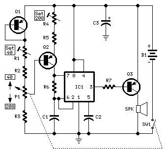
Parts:P1 100K Linear PotentiometerR1 10K 1/2W Trimmer CermetR2 10K 1/4W ResistorR3 330K 1/4W ResistorR4 50K 1/2W Trimmer CermetR5 100K 1/4W ResistorR6,R7 1K 1/4W ResistorC1 1µF 63V Polyester CapacitorC2 10nF 63V Polyester CapacitorC3 47µF 25V Electrolytic CapacitorIC1 NE555 General purpose timer ICQ1,Q2 BC560 45V 100mA Low noise High gain PNP TransistorsQ3 ZTX753 100V 2A PNP TransistorSW1 SPST Switch (Ganged with P1)SPK 8 Ohm 40mm. Loudspeaker B1 12V Battery (MN21, GP23A or VR22 type)
Notes:Q1 & Q2 provide linear frequency operation of IC1 following P1 resistance variation.Q3 was added in order to obtain a louder click, similar to clockwork metronomes.12V micro battery was used to obtain more output power and more compactness.Rotate P1 fully towards R2, then set R1 to obtain 40 beats per minute (compare with another metronome).Rotate P1 fully towards R3, then set R4 to obtain 208 beats per minute.Finally mark the entire scale with the usual metronome steps as following:40 - 42 - 44 - 46 - 48 - 50 - 52 - 54 - 58 - 60 - 63 - 66 - 69 - 72 - 76 - 80 - 84 - 88 - 92 - 96 - 100 - 104 - 108 - 112 - 116 - 120 - 126 - 132 - 138 - 144 - 152 - 160 - 168 - 176 - 184 - 192 - 200 - 208. (View)
View full Circuit Diagram | Comments | Reading(1153)
5 to 30 Minute Timers
Published:2013/7/30 20:36:00 Author:muriel | Keyword: 5 to 30 Minute , Timers
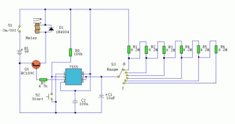
Notes:Simple to build, simple to make, nothing too complicated here. However you must use the CMOS type 555 timer designated the 7555, a normal 555 timer will not work here due to the resistor values. Also a low leakage type capacitor must be used for C1, and I would strongly suggest a Tantalum Bead type. Switch 3 adds an extra resistor in series to the timing chain with each rotation, the timing period us defined as :-
Timing = 1.1 C1 x R1
Note that R1 has a value of 8.2M with S3 at position a and 49.2M at position f . This equates to just short of 300 seconds for each position of S3. C1 and R1 through R6 may be changed for different timing periods. The output current from Pin 3 of the timer, is amplified by Q1 and used to drive a relay.
Parts Relay 9 volt coil with c/o contact (1)S1 On/Off (1)S2 Start (1)S3 Range (1)IC1 7555 (1)B1 9V (1)C1 33uF CAP (1)Q1 BC109C NPN (1)D1 1N4004 DIODE (1)C2 100n CAP (1)R6,R5,R4,R3,R2,R1 8.2M RESISTOR (6)R8 100k RESISTOR (1)R7 4.7k RESISTOR (1) (View)
View full Circuit Diagram | Comments | Reading(827)
Sound Effects Generators
Published:2013/7/30 20:35:00 Author:muriel | Keyword: Sound Effects Generators

Notes:Nothing too complicated here. The IC produces all the sound effects, the output at Pin 3 being amplified by the transistor. A 64 ohm loudspeaker can be substituted in place of the 56 ohm resistor and 8 ohm loudspeaker. The 2 pole 4 way switch controls the sound effects. Position 1 (as drawn) being a Police siren, position 2 is a fire engine sound, 3 is an ambulance and position 4 is a machine gun effect. The IC is manufactured by UMC and was available from Maplin electronics code UJ45Y. At the time of writing this has now been discontinued, but they have have limited stocks available. (View)
View full Circuit Diagram | Comments | Reading(854)
Jogging Timers
Published:2013/7/30 20:31:00 Author:muriel | Keyword: Jogging Timers
Parts:R1 47K 1/4W ResistorR2 10M 1/4W ResistorR3 1M 1/4W ResistorR4 12K 1/4W Resistor (see notes)C1,C3 10µF 25V Electrolytic CapacitorsC2 100nF 63V Polyester CapacitorD1 1N4148 75V 150mA DiodeIC1 4093 Quad 2 input Schmitt NAND Gate ICIC2 4060 14 stage ripple counter and oscillator ICIC3 4017 Decade counter with 10 decoded outputs ICQ1 BC337 45V 800mA NPN TransistorSW1 1 pole 9 ways Rotary Switch (see notes)SW2 SPST Slider SwitchBZ1 Piezo sounder (incorporating 3KHz oscillator)B1 3V Battery (two 1.5V AA or AAA cells in series etc.)
Device purpose:This circuit was developed since a number of visitors of this website requested a timer capable of emitting a beep after one, two, three minutes and so on, for jogging purposes.As shown in the Circuit diagram, SW1 is a 1 pole 9 ways Rotary Switch. Setting the switch in position 1, the Piezo sounder emits three short beeps every minute. In position 2 the same thing happens after 2 minutes, and so on, reaching a maximum interval of 9 minutes in position 9.
Notes:Needing only one time set, rotary switch can be replaced by an hard-wired link.A DIP-Switch can be used in place of the rotary type. Pay attention to use only a switch at a time, or the device could be damaged.Varying R4 from 10K to 15K you can obtain more or less than three short beeps after the preset time delay.To obtain a one-second beep only, after the preset time delay, disconnect pin 9 of IC1C from pin 9 of IC2 and connect it to pin 8 of IC1C. (View)
View full Circuit Diagram | Comments | Reading(862)
Repeating Interval Timers
Published:2013/7/30 20:30:00 Author:muriel | Keyword: Repeating Interval Timers

This circuit has an adjustable output timer that will re-trigger at regular intervals. The output period can be anything from a fraction of a second to half-an-hour or more - and it can be made to recur at regular intervals of anything from seconds to days and beyond.
The Output Section:The output section is a simple Monostable Circuit. When Pin 6 of the Cmos 4001 is taken high - the monostable triggers - and the relay energizes. It will remain energized for a period of time set by C1 & R3.With the values shown - R3 will provide output periods of up to about 30-minutes. However, you can choose component values to suit your requirements. For example, if you reduce R3 to 1meg - and C1 to 4.7uF - the maximum output period is between 3 and 5 seconds. Owing to manufacturing tolerances - the precise length of the time period available depend on the characteristics of the actual components you've used.
The Cmos 4060:The Cmos 4060 is a 14-bit binary counter with a built-in oscillator. The oscillator consists of the two inverters connected to Pins 9, 10 & 11 - and its frequency is controlled by R7. The output from the oscillator is connected internally to the binary counter. While the oscillator is running - the IC counts the number of oscillations - and the state of the count is reflected in the output pins.By adjusting R7 - you can set the length of time it takes for any given output pin to go high. Connect that output to Pin 6 of the Cmos 4001 and - every time it goes high - it'll trigger the monostable.Ideally C4 should be non-polarized - but a regular electrolytic will work - provided it doesn't leak too badly in the reverse direction. Alternatively - you can simulate a non-polarized 10uF capacitor by connecting two 22uF capacitors back to back - as shown. (View)
View full Circuit Diagram | Comments | Reading(1098)
Adjustable High/Low Frequency Sine wave generator
Published:2013/7/30 20:29:00 Author:muriel | Keyword: Adjustable , High/Low Frequency , Sine wave, generator

This circuit uses the versatile MAX038 function generator. Although in this circuit some of the advanced characteristics of this IC are disabled, you can generate Sine, Triangle, Square waves (adjusting A0 and A1 pins see datasheet on www.maxim-ic.com if you want other waves, use a switch).The signal is amplified through a TCA0372 (from ONSEMI) Power opamp with current capability up to 1A and bandwitch up to 1 MHz.I selected this particular frequency (122 Khz) because i needed a cheapo ESR-o-meter for my electrolytic capacitors to monitor their health as they have to discharge tens of amperes in less than 2 ms. At 122 KHz capacitive reactance is very low, and inductive reactance isn't so high, so forcing a current (es 200mA, using a precision resistor) through a capacitor and reading AC voltage drop accross it gives me an estimation of ESR (Vdrop/current). Of course inductive and capacitive reactance are still present, but negligible.Let's back to the circuit.
Operation:The 122 khz 2V p-p sine wave is generated by the MAX038 IC, its frequency can be calculated by the formula Freq (MHz) = Iin(uA) / C6 (pf) . Iin = 2,5V / R1 (25Kohm default). So the freq is 0,122 MHz . The resistor is for small adjustments, don't go under 10000 Kohm or above 40000 Kohm because the accuracy will drop. If you want multifrequency just use the multiposition switch with 820 pF, 8,2 nF , 82nF , 820 nf for 122Khz range 12,2Khz range 1220 Hz and 122 Hz. Fine tuning can be done adjusting R2 , the frequency can vary from 1,7x (Vfadj = -2,4) to 0,3x (Vfadj = 2,4) of the main frequency (when fadj is at 0V).The sine wave output is feed into a TCA0372 1/2 opamp to achieve a gain from 1 to 5 (2V p-p, 10 V p-p), adjust the potenziometer and into a TCA0372 2/2 opamp buffer stage also present on the same IC.
Important:Adjusting the frequency needs a frequency counter, so this circuit should be used on conjunction with a freq couter. The max current is 1A, but i would suggesto to not go above 0,5A to remain accurate. Needs a computer power supply with 12V,5V,-5V,-12V,GND to be operated, if you don't have one just use a multivoltage mains transformer (15 watt is enough) diode bridges (low current 1-2 Amps), smoothing capacitors 10000uF 16V, and voltage regulators such as LM7905 and LM7912. (View)
View full Circuit Diagram | Comments | Reading(1459)
Function Generators
Published:2013/7/30 20:29:00 Author:muriel | Keyword: Function Generators

Built around a single 8038 waveform generator IC, this circuit produces sine, square or triangle waves from 20Hz to 200kHz in four switched ranges. There are both high and low level outputs which may be adjusted with the level control. This project makes a useful addition to any hobbyists workbench as well.Allof the waveform generation is produced by IC1. This versatile IC even has a sweep input, but is not used in this circuit. The IC contains an internal squarewave oscillator, the frequency of which is controlled by timing capacitors C1 - C4 and the 10k potentiometer. The tolerance of the capacitors should be 10% or better for stability. The squarewave is differentiated to produce a triangular wave, which in turn is shaped to produce a sine wave. All this is done internally, with a minimum of external components. The purity of the sine wave is adjusted by the two 100k preset resistors.The wave shape switch is a single pole 3 way rotary switch, the wiper arm selects the wave shape and is connected to a 10k potentiometer which controls the amplitude of all waveforms. IC2 is an LF351 op-amp wired as a standard direct coupled non-inverting buffer, providing isolation between the waveform generator, and also increasing output current. The 2.2k and 47 ohm resistors form the output attenuator. At the high output, the maximum amplitude is about 8V pk-pk with the square wave. The maximum for the triangle and sine waves is around 6V and 4V respectively. The low amplitude controls is useful for testing amplifiers, as amplitudes of 20mV and 50mV are easily achievable. (View)
View full Circuit Diagram | Comments | Reading(1446)
Infra-red Level Detectors
Published:2013/7/30 20:12:00 Author:muriel | Keyword: Infra-red Level Detectors
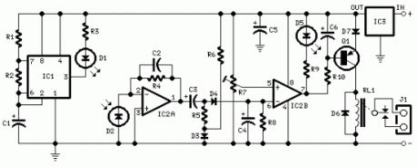
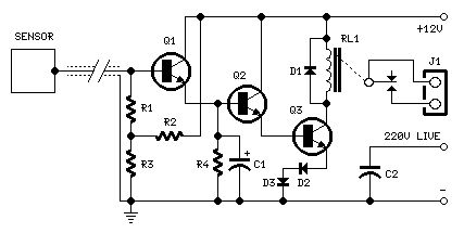
Parts:R1 10K 1/4W ResistorR2,R5,R6,R9 1K 1/4W ResistorsR3 33R 1/4W ResistorR4,R8 1M 1/4W ResistorsR7 10K Trimmer CermetR10 22K 1/4W ResistorC1,C4 1µF 63V Electrolytic or Polyester CapacitorsC2 47pF 63V Ceramic CapacitorC3,C5,C6 100µF 25V Electrolytic CapacitorsD1 Infra-red LEDD2 Infra-red Photo Diode (see Notes)D3,D4 1N4148 75V 150mA DiodeD5 LED (Any color and size)D6,D7 1N4002 100V 1A DiodesQ1 BC327 45V 800mA PNP TransistorIC1 555 Timer ICIC2 LM358 Low Power Dual Op-ampIC3 7812 12V 1A Positive voltage regulator ICRL1 Relay with SPDT 2A @ 220V switchCoil Voltage 12V. Coil resistance 200-300 OhmJ1 Two ways output socketDevice purpose:This circuit is useful in liquids level or proximity detection. It operates detecting the distance from the target by reflection of an infra-red beam. It can safely detect the level of a liquid in a tank without any contact with the liquid itself. The device's range can be set from a couple of cm. to about 50 cm. by means of a trimmer.Range can vary, depending on infra-red transmitting and receiving LEDs used and is mostly affected by the color of the reflecting surface. Black surfaces lower greatly the device's sensitivity.
Circuit operation:IC1 forms an oscillator driving the infra-red LED by means of 0.8mSec. pulses at 120Hz frequency and about 300mA peak current. D1 & D2 are placed facing the target on the same line, a couple of centimeters apart, on a short breadboard strip. D2 picks-up the infra-red beam generated by D1 and reflected by the surface placed in front of it. The signal is amplified by IC2A and peak detected by D4 & C4. Diode D3, with R5 & R6, compensate for the forward diode drop of D4. A DC voltage proportional to the distance of the reflecting object and D1 & D2 feeds the inverting input of the voltage comparator IC2B. This comparator switches on and off the LED and the optional relay via Q1, comparing its input voltage to the reference voltage at its non-inverting input set by the Trimmer R7.
Notes:Power supply must be regulated (hence the use of IC3) for precise reference voltages. The circuit can be fed by a commercial wall plug-in power supply, having a DC output voltage in the range 12-24V.Current drawing: LED off 40mA; LED and Relay on 70mA @ 12V DC supply.R10, C6, Q1, D6, D7, RL1 and J1 can be omitted if relay operation is not required.The infra-red Photo Diode D2, should be of the type incorporating an optical sunlight filter: these components appear in black plastic cases. Some of them resemble TO92 transistors: in this case, please note that the sensitive surface is the curved, not the flat one.Avoid sun or artificial light hitting directly D1 & D2.Usually D1-D2 optimum distance lies in the range 1.5-3 cm. (View)
View full Circuit Diagram | Comments | Reading(3029)
Capacitive Sensors
Published:2013/7/29 20:24:00 Author:muriel | Keyword: Capacitive Sensors
Parts:R1,R2 1M 1/4W ResistorsR3,R4 47K 1/4W ResistorsC1 10µF 25V Electrolytic CapacitorC2 470pF 630V Ceramic or Polyester CapacitorD1-D3 1N4002 100V 1A DiodesQ1-Q3 BC337 45V 800mA NPN TransistorsRL1 Relay with SPDT 2A @ 220V switchCoil Voltage 12V. Coil resistance 200-300 OhmJ1 Two ways output socketSensor Aluminium or copper thin sheet with the dimensions of a post-card,glued at the rear of the same (approx. 15x10.5 cm.)Thin screened cable
Circuit description:The purpose of this circuit is to animate shop-windows by means of a capacitive sensor placed behind a post-card-like banner. The card is placed against the glass inside the shop-window, and the visitor can activate the relay placing his hand on the card, from the outside. Especially suited for toy-shops, the circuit can activate model trains, small electric racing cars, lights etc. Further applications are left at user's imagination. Adopt it to increase the impact of your shop-window on next Christmas season!Q1, Q2 & Q3 form a high impedance super-Darlington that drives the relay, amplifying the 50Hz alternate mains-supply frequency induced in the sensor by the human body. C1 & D2, D3 ensure a clean relay's switching. Power supply can be any commercial wall plug-in transformer with rectifier and smoothing capacitor, capable of supplying the voltage and current necessary to power the relay you intend to use. (View)
View full Circuit Diagram | Comments | Reading(1778)
Simple optical switch
Published:2013/7/29 20:23:00 Author:muriel | Keyword: Simple optical switch

IntroductionThe 555 is proved to be the most versatile and ubiquitous IC all over the world.This is a possible use: simple inverting schmitt trigger.
Circuit explanationWhen the phototransistor is stroken by IR light it conducts and the voltage between the 1Mohm resistor(arbitrary) and the phototrans drops from VCC to lower values. When the voltage drops lower than VCC/3 the 555 is triggered and goes high (from 0 TO VCC). The amount of light that strike the phototrans necessary to bring his collector to VCC/3 is determined by the resistor (Vdrop = Icollector * R , so , if Vdrop= 2*VCC/3, the resistance needed to set the threshold on current is R=2*VCC/(Icollector*3)). High sensibility phototrans would need a smaller resistor, and weaker phototransistors higher value resistor, you can also use a trimmer to set the on threshold level with precision. The time of phototransistor isn't critical. The 555 has high current capability and can drive various devices, such as Bipolars, relays, bipolars+relays, mosfets, mosfets + totem pole , or give a logic output (see pic).In case you need to trigger something when the gate is blocked (for example a burglar alarm, or a multistage coilgun) you need to invert the output, which is accomplished using a small bipolar transistor wired in an inverting setup (see pic) or swapping the positions of phototransistor with the resistor, so the voltage will drop under VCC/3 when blocked: The formula to determine the resistance to turn off at Icollector is R=VCC/(Icollector*3). (View)
View full Circuit Diagram | Comments | Reading(903)
DC Motor Reversing Circuit
Published:2013/7/29 20:23:00 Author:muriel | Keyword: DC Motor Reversing Circuit

A DC motor reversing circuit using non latching push button switches. Relays control forward, stop and reverse action, and the motor cannot be switched from forward to reverse unless the stop switch is pressed first.
Notes:At first glance this may look over-complicated, but this is simply because three non-latching push button switches are used. When the forward button is pressed and released the motor will run continuously in one direction. The Stop button must be used before pressing the reverse button. The reverse button will cause the motor to run continuously in the opposite direction, or until the stop button is used. Putting a motor straight into reverse would be quite dangerous, because when running a motor develops a back emf voltage which would add to current flow in the opposite direction and probably cause arcing of the relay contacts. This circuit has a built-in safeguard against that condition.
Circuit Operation:Assume that the motor is not running and that all relays are unenergized. When the forward button is pressed, a positive battery is applied via the NC contacts of B1 to the coil of relay RA/2. This will operate as the return path is via the NC contacts of D1. Relay RA/2 will operate. Contacts A1 maintain power to the relay even though the forward button is released. Contacts A2 apply power to the motor which will now run continuously in one direction. If now the reverse button is pressed, nothing happens because the positive supply for the switch is fed via the NC contact A1, which is now open because Relay RA/2 is energized. To Stop the motor the Stop switch is pressed, Relay D operates and its contact D1 breaks the power to relays A and B, (only Relay A is operated at the moment). If the reverse switch is now pressed and released. Relay B operates via NC contact A1 and NC contact D1. Contact B1 closes and maintains power so that the relay is now latched, even when the reverse switch is opened. Relay RC/2 will also be energized and latched. Contact B2 applies power to the motor but as contacts C1 and C2 have changed position, the motor will now run continuously in the opposite direction. Pressing the forward button has no effect as power to this switch is broken via the now open NC contact B1. If the stop button is now pressed. Relay D energizes, its contact D1 breaks power to relay B, which in turn breaks power to relay C via the NO contact of B1 and of course the motor will stop. All very easy. The capacitor across relay D is there to make sure that relay D will operate at least longer than the time relays A,B and C take to release. (View)
View full Circuit Diagram | Comments | Reading(1339)
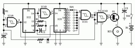
Infra Red Switches
Published:2013/7/29 20:22:00 Author:muriel | Keyword: Infra Red Switches

This is a single channel (on / off) universal switch that may be used with any Infra Red remote control that uses wavelengths between 850-950nm.
Notes:Any button of any remote control may be used to work this universal switch. The button must be pressed for two seconds (determined by R3 and C2) before the relay will operate. Once operated the circuit will remain in this state (latched) until reset. To reset, any button is pressed and held for the delay.For example, if you were watching TV, and your set was tuned to Channel 3, you could press and hold the TV remote controls channel 3 button for two seconds. That way the TV viewing would not be affected and the relay would activate. You can connect anything to the relay, for example a lamp, but make sure that the relay contacts can handle the rated voltage and current.
Circuit Operation:IC1 is an Infra Red module. IR modulated pulses are received and buffered by this IC. It has a standard TTL output, the output with no signal is logic 1. One gate of a CMOS inverter and drives Red LED1 as a visible switching aid. Another gate buffers the signal and applies it to the time constant circuit, comprising R3,C2,R4 and D1. C2 charges via R3, and discharges via R4, D1 prevents quick discharge via the low output impedance of the CMOS buffer.
The pulses are further buffered and contain jaggered edges as shown above. These edges are produced by the modulated IR data, which has to be removed. This is achieved using IC3, a 555 timer wired as a monostable, pulse duration R5, C4. These cleanly reconstructs a single clean pulse to activate the bistable latch. A D type flip flop, IC4 is configured as a bistable. The input is applied to the clock pin, the inverted output fed back to the data input and clear and preset lines are tied to ground. For every pulse the relay will operate and latch, the next pulse will turn off the relay and so on. Note that quick turn on and off of the relay is not possible. The output pulse is set at about 1.5 seconds and input delay by R3, C2 set at two seconds.
PartsR1 3k3R2 1kR3 22kR4 220kR5 1MR6 3k3B1 12 VD1 1N4148D2 1N4003Q1 B109LED1 CQX35AIC1 IR1 available from Harrison ElectronicsIC2 4049IC3 CA555IC4 SN74HCT74IC5 LM7805Relay 12 Volt coil with changeover contactC1 100uC2 22uC3 100nC4 2u2 (View)
View full Circuit Diagram | Comments | Reading(1006)
| Pages:64/2234 At 206162636465666768697071727374757677787980Under 20 |
Circuit Categories
power supply circuit
Amplifier Circuit
Basic Circuit
LED and Light Circuit
Sensor Circuit
Signal Processing
Electrical Equipment Circuit
Control Circuit
Remote Control Circuit
A/D-D/A Converter Circuit
Audio Circuit
Measuring and Test Circuit
Communication Circuit
Computer-Related Circuit
555 Circuit
Automotive Circuit
Repairing Circuit