Basic Circuit
Dome Lamp Dimmer
Published:2013/7/30 20:38:00 Author:muriel | Keyword: Dome Lamp Dimmer | From:SeekIC

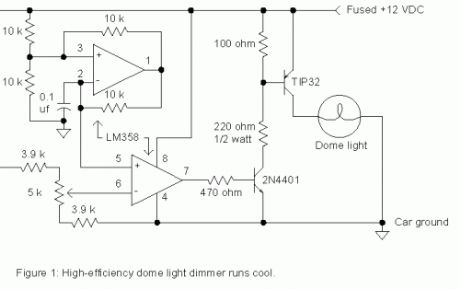
There are times when a little light inside the car would greatly assist one of the passengers but the dome light is too bright for safe driving. The dimmer circuit in fig. 1 may be added to an existing dome light or included with a new passenger spot lamp. The upper op-amp generates a 700 Hz sawtooth waveform which is compared to a setpoint voltage by the lower op-amp. When the sawtooth voltage is above the setpoint, the transistors turn on supplying current to the bulb. The setting of the potentiometer determines the width of the pulses sent to the lamp and therefore the average voltage. The lamp is dim when the potentiometer is set near the higher voltage. Since the TIP32 switches on and off instead of simply dropping the voltage like a power rheostat, the power it dissipates remains low and a heat sink is not necessary.
Many autos run power to lamps with only one wire using the car body for the return current path so the dimmer must interrupt the positive lead as shown. Simply cut the wire leading to the lamp and connect the lamp end to the collector of the TIP32 and connect the battery end to the circuit power input. Run an additional ground wire to the auto chassis from the circuit. This ground wire will not carry much current and may be a smaller gauge.
Reprinted Url Of This Article:
http://www.seekic.com/circuit_diagram/Basic_Circuit/Dome_Lamp_Dimmer.html
Print this Page | Comments | Reading(3)

Article Categories
power supply circuit
Amplifier Circuit
Basic Circuit
LED and Light Circuit
Sensor Circuit
Signal Processing
Electrical Equipment Circuit
Control Circuit
Remote Control Circuit
A/D-D/A Converter Circuit
Audio Circuit
Measuring and Test Circuit
Communication Circuit
Computer-Related Circuit
555 Circuit
Automotive Circuit
Repairing Circuit
Code: