Control Circuit
SOLID STATE RELAY REQUIRES ONLY 50uA DRIVE CURRENT CIRCUIT
Published:2013/8/7 20:53:00 Author:lynne | Keyword: SOLID STATE RELAY REQUIRES ONLY 50uA DRIVE CURRENT CIRCUIT | From:SeekIC

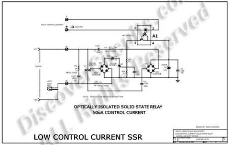
Most solid state relays require at least 5ma and often more input control current, to fully turn on the device. But such current levels often force battery powered circuits to use excessively large batteries. The relay hobby circuit shown below demands only 50uA of input current. This about 100 times lower than that needed by a typical optically isolated solid state relays. The circuit uses a combination of a high current triac and a very sensitive low current SCR, to control up to 600 watts of power to a load, while providing full isolation and transient protection.
[H-Corner/ads/i-HC-boombox.htm]
At the heart of the circuit is a Darlington type opto-isolator A1 from NEC. This device needs only 50uA of current through the LED section to activate the Darlington side. A bridge rectifier and a couple capacitors, strips off a bit of current from the 120vac line, through the load. A zener diode limits the generated DC voltage to 8v. When the opto-isolator is turned on, current is routed to the gate of a sensitive SCR. When turned on, the SCR routes current pulses to the main control triac, through a bridge rectifier. A 15v zener delays the trigger point of the triac slightly, so a minimum 30 volts peak to peak is always available to maintain current to the SCR circuit.
Reprinted Url Of This Article:
http://www.seekic.com/circuit_diagram/Control_Circuit/SOLID_STATE_RELAY_REQUIRES_ONLY_50uA_DRIVE_CURRENT_CIRCUIT.html
Print this Page | Comments | Reading(3)

Article Categories
power supply circuit
Amplifier Circuit
Basic Circuit
LED and Light Circuit
Sensor Circuit
Signal Processing
Electrical Equipment Circuit
Control Circuit
Remote Control Circuit
A/D-D/A Converter Circuit
Audio Circuit
Measuring and Test Circuit
Communication Circuit
Computer-Related Circuit
555 Circuit
Automotive Circuit
Repairing Circuit
Code: