Sensor Circuit
Backup Light
Published:2013/9/22 19:55:00 Author:lynne | Keyword: Backup Light | From:SeekIC

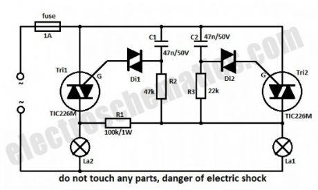
In series with La1 is the Tri2 triac. R3 and C2 form a network delay. As soon as the voltage on C2 is increasing over 30 V, the diac D2 will start to conduct and this will trigger Tri2 resulting in the lighting of La1. The command circuit of La2 is in parallel with the one for La1 but because R2-C1 has a double timing compared to R3-C2 the firing of Tri1 won’t happen when Tri2 conducts.
If La1 is burned out then there is voltage on both RC networks, through La2 and R1 and so the Tri2 will be triggered first but because its current is lower than the holding current it will stop conducting almost immediately. In this situation C1 will continue to charge and shortly Tri1 will trigger.
Because the time constant for La2 is a little higher than the one of La1, then the La2 light intensity will be a little lower. If you want that both light intensity to be the same then choose La1 with a higher nominal power.
Without heatsinks the triacs can outstand powers up to 100 W each, and with heatsinks up to 1000 W. It is not indicated to use light bulbs with power less than 25 W because it might flicker.
Reprinted Url Of This Article:
http://www.seekic.com/circuit_diagram/Sensor_Circuit/Backup_Light.html
Print this Page | Comments | Reading(3)

Article Categories
power supply circuit
Amplifier Circuit
Basic Circuit
LED and Light Circuit
Sensor Circuit
Signal Processing
Electrical Equipment Circuit
Control Circuit
Remote Control Circuit
A/D-D/A Converter Circuit
Audio Circuit
Measuring and Test Circuit
Communication Circuit
Computer-Related Circuit
555 Circuit
Automotive Circuit
Repairing Circuit
Code: